
Multiple channel adaptive data recovery system

a data recovery and multi-channel technology, applied in the field of digital data communication systems, can solve problems such as data recovery errors, system errors, bandwidth loss,

Inactive Publication Date: 2006-02-07
MAXIM INTEGRATED PROD INC +1
View PDF5 Cites 47 Cited by
  • Summary
  • Abstract
  • Description
  • Claims
  • Application Information

AI Technical Summary

Benefits of technology

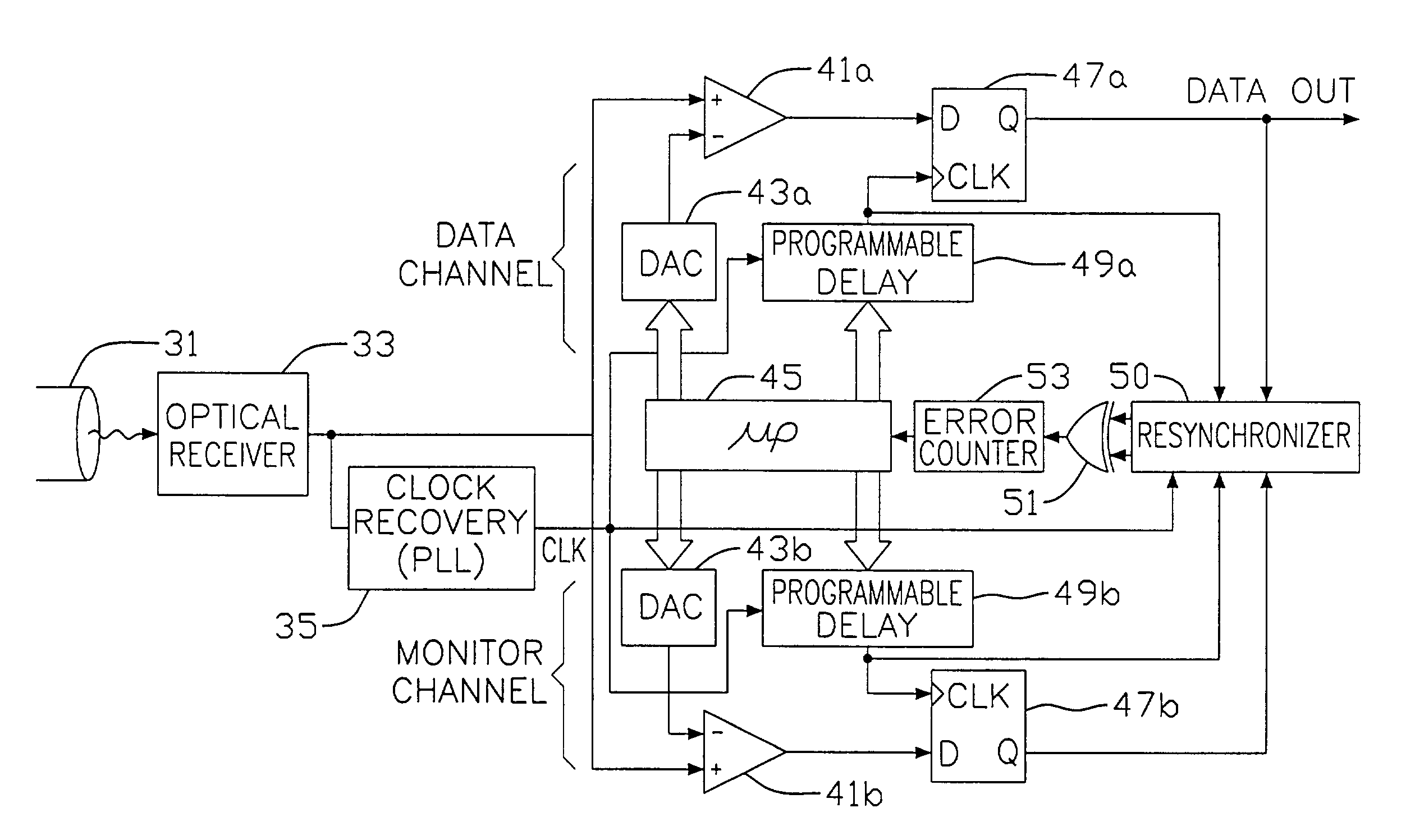
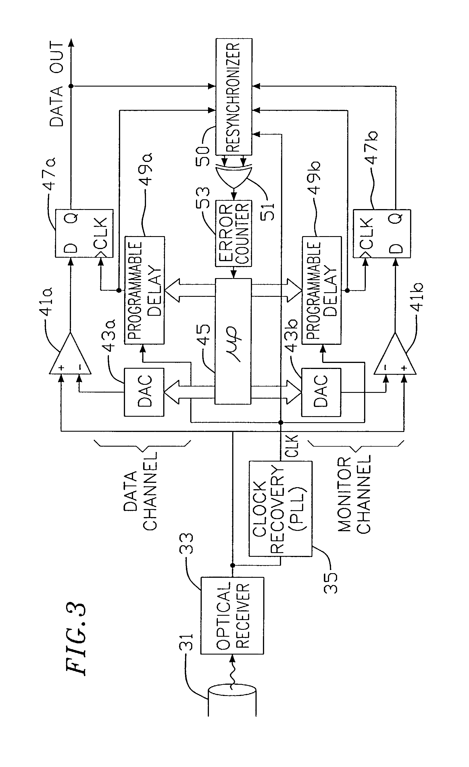
The present invention provides systems and methods for extracting clock and data recovery from digital communication signals. The system splits the data signal into multiple channels and a replacement channel, which is then digitized and compared to a reference energy level. The result is used to adjust the digitization of the data channels. The replacement channel is varied to determine the edges of a data eye, which is then used as a digitization point for the data signal. This is done by changing the reference energy level and the phase of a clock signal. The system uses a comparator and a latch or flip flop for sampling. The invention allows for more accurate and efficient recovery of clock and data from digital signals.

Problems solved by technology

Such systems are prone to errors, however.
Slight differences in frequency between the transmitter clock and the clock generator of the receiving unit may lead to data recovery errors over time, or at least require periodic reacquisition of the correct phase adjusted clock signal, with a loss of bandwidth during the reacquisition period.
In addition, deviations from an ideal transmitted data signal and distortions in transmitted signals, whether generated by properties of the transmitter, the communication medium, or otherwise, may result in data recovery errors.
There are many causes of such deviations and distortions, and the deviations may change from transmitted bit to transmitted bit as well as exhibit both drift and an increase in the magnitude of the deviations over time as components age.
Additionally, the transmitter and receiving unit may not have clocks perfectly aligned in frequency or phase, thus increasing the difficulty in the translation.
Further, properties of the communication medium may distort the transmitted signals, and a receiver utilized by the receiving unit may also cause distortion of the signals.

Method used


Image

  • Multiple channel adaptive data recovery system
  • Multiple channel adaptive data recovery system
  • Multiple channel adaptive data recovery system

Examples


Embodiment Construction

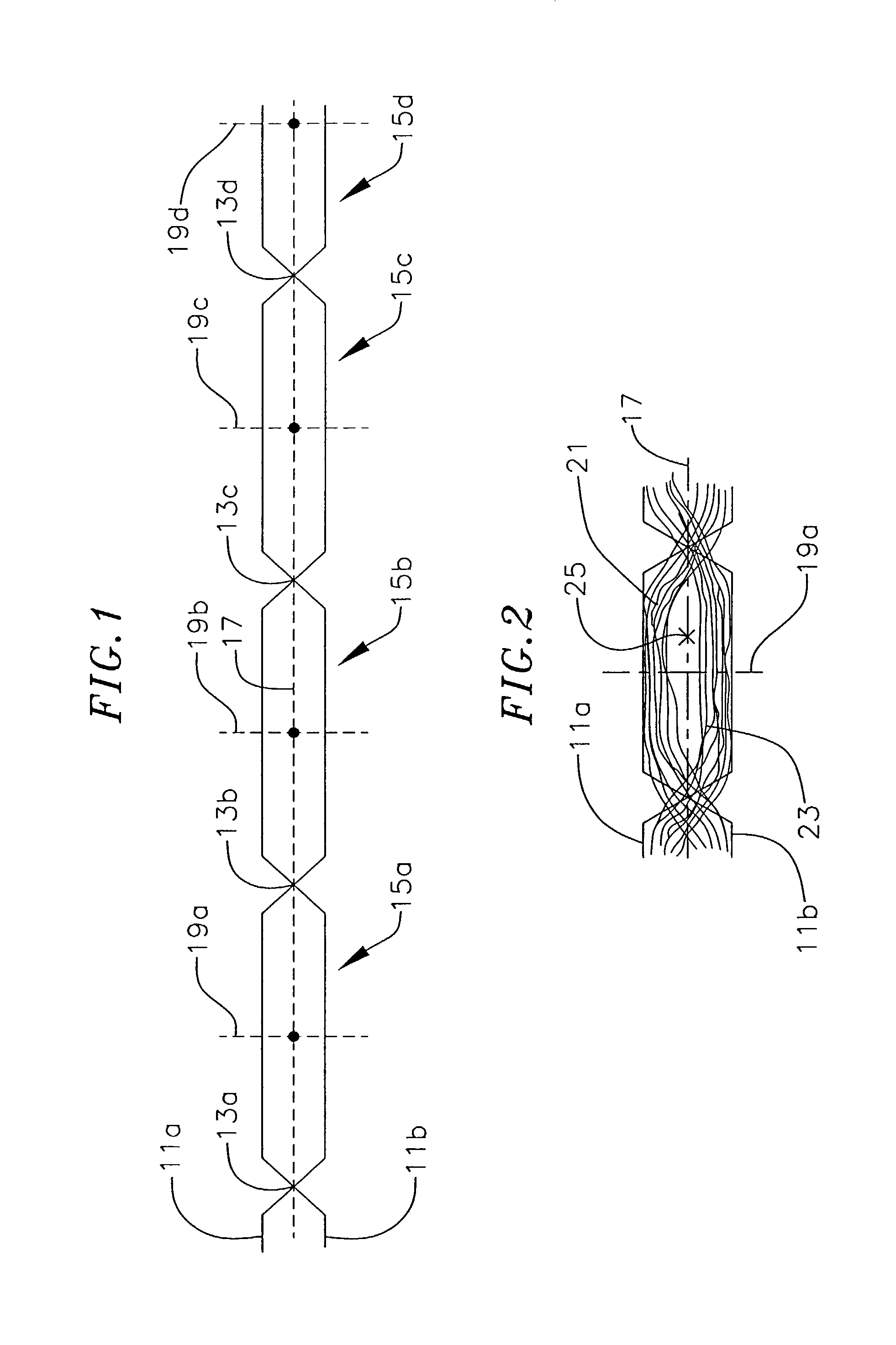
[0032]FIG. 2 illustrates a possible actual data-eye of a single data cell. The data eye is formed by superimposing waveforms of a plurality of data signals over a single data cell. A first plurality of varying data signals 21 are data signals having the same bit sequence as the first data signal 11a, and a second plurality of varying data signals 23 are data signals having a bit sequence corresponding to the bit sequence of the second data signal 11b. As illustrated, the plurality of data signals vary substantially from the data signals. The plurality of data signals generally to do not reach the expected upper voltage level, or the expected lower voltage level. The plurality of data signals additionally exhibit increased rise times, decreased steady state times, and increased fall times. In addition to varying from the data signals, the plurality of data signals vary from each other, having different waveforms. Moreover, the variations in rise time, fall time, and steady state time...


PUM


Abstract

A microprocessor controlled data recovery unit with an adjustable sampling and signal comparison level. The data recovery unit includes a data channel and a monitor channel. The monitor channel samples an incoming data stream in a varying manner. The results of the sampling in the monitor channel are used to adjust the sampling and comparing of the signal in the data channel. The data recovery unit includes a PLL based clock recovery unit in one embodiment, and in another embodiment the clock signal is derived by the microprocessor.

Description

CROSS-REFERENCE TO RELATED APPLICATION(S)[0001]The present application is a continuation application of U.S. patent application Ser. No. 09 / 531,277, filed Mar. 20, 2000, issued Oct. 8, 2002 as U.S. Pat. No. 6,463,109 entitled “MULTIPLE CHANNEL ADAPTIVE DATA RECOVERY SYSTEM”, and which is a continuation-in-part of U.S. patent application Ser. No. 09 / 139,252, filed Aug. 25, 1998, now U.S. Pat. No. 6,178,213, issued Jan. 23, 2001, both disclosures of which are incorporated herein by reference.BACKGROUND OF THE INVENTION[0002]This invention relates generally to digital data communication systems, and more particularly to recovering clock signals and digital data from a serial data signal.[0003]Modern data communication systems are required to accurately transmit and receive digital information at high data transmission rates. The digital information is often transmitted great distances over a variety of communication mediums such as electrically conducting wires and, commonly now, optic...

Claims


Application Information

Patent Timeline
Patent Type & Authority Patents(United States)
IPC IPC(8): H04L7/00H04L25/40H03L7/099H03L7/10H04L7/02H04L7/033H04L25/02H04L25/06
CPCH03L7/0995H03L7/10H04L7/0037H04L7/0334H04L25/0262H04L25/063H04L7/033H03L2207/14H03L7/103H03L7/12
Inventor MCCORMACK, GARY D.TALAGA, JR., RONALD F.
Owner MAXIM INTEGRATED PROD INC
Learn More