Method for fault tracing in electronic measurement and test arrangements for electrochemical elements

a technology of electronic measurement and test arrangement, applied in the direction of electrical testing, electronic circuit testing, instruments, etc., can solve the problems of high labor intensity, long time and large amount of work, and manual testing of connections during system construction, so as to achieve simple and quick

Inactive Publication Date: 2006-02-07
VARTA MICROBATTERY +1
View PDF6 Cites 0 Cited by
  • Summary
  • Abstract
  • Description
  • Claims
  • Application Information

AI Technical Summary

Benefits of technology

[0009]This invention provides a method and an apparatus which is suitable, in particular, for carrying out the method, and which allows fault tracing to be carried out simply, quickly and in a manner which can be fully automated, and allows precautionary problem identification.
[0011]The cell simulators contain test electronics which may at least comprise a resistor and a diode connected in parallel. Two or more cell simulators are advantageously arranged alongside one another or adjacent to one another. In this case, they may each differ slightly from one another, for example they may have a different voltage response behaviour. This can be achieved, for example, by means of different impedances, thus making it easy to distinguish between the individual cell simulators.

Problems solved by technology

The large number of cables and control electronics channels that this results in can lead to faults both during installation and during operation.
Manual testing of the connections during construction of the system is highly complex, requiring a long time and a large amount of work in difficult conditions.
Faults can often not be detected during operation, and this thus leads to incorrect measurements and incorrect actions.

Method used


Image

  • Method for fault tracing in electronic measurement and test arrangements for electrochemical elements
  • Method for fault tracing in electronic measurement and test arrangements for electrochemical elements
  • Method for fault tracing in electronic measurement and test arrangements for electrochemical elements

Examples


Embodiment Construction

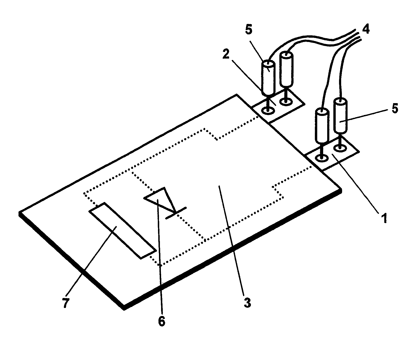
[0017]FIG. 1 shows, schematically, the design of a cell simulator 9, comprising a printed circuit board 3 which contains test electronics, which comprise at least a resistor 7 and a diode 6 connected in parallel. The cell simulator 9 also contains the positive output conductor 1 and the negative output conductor 2. The output conductors are connected to a power supply and to a test apparatus via four contact pins 5, which are combined in a line 4. Instead of using the contact pins, contact can also be made with the output conductors via contact springs which are fitted on both sides. The two output conductors may, for example, be composed of a nickel strip with a thickness of 100 μm and a width of 5 mm and are connected, for example by means of a soldering process, to the conductor tracks of the test electronics on the printed circuit board. The dimensions of the external shape and size of the cell simulator correspond to the electrochemical element to be tested or to be formed.

[001...


PUM

PropertyMeasurementUnit
widthaaaaaaaaaa
thicknessaaaaaaaaaa
voltageaaaaaaaaaa

Abstract

A method for fault tracing in automatically operating electronic measurement and test arrangements for a large number of electrochemical elements, wherein holders for the electrochemical elements are provided on the measurement and test arrangements and wherein cell simulators are provided with an external shape and size, including electrical connections, which approximately simulate one of the electrochemical elements to be tested, and contain test electronics, with a behaviour of the cell simulators with inverse polarity differing to a major extent from a behaviour with polarity based on the application, including the steps of inserting of the cell simulators into the holders, activating one of the cell simulators and applying a measurement current applied to it, measuring the voltage on the cell simulator and comparing the voltage with the nominal voltage predetermined for the cell simulator.

Description

FIELD OF THE INVENTION[0001]The invention is related to a method for fault tracing in automatically operating electronic measurement and test arrangements for a large number of electrochemical elements, as well as an apparatus which is suitable in particular for carrying out this method.BACKGROUND[0002]Rechargeable electrochemical elements, in particular lithium cells, in many cases contain a cell stack which comprises two or more individual elements. The individual cells or individual elements from which a cell stack such as this is composed are a laminate which is produced from output conductors, an active electrode film and a separator. Laminates such as these composed of firmly connected individual parts are produced in particular as so-called—“bicells”— with the following possible sequences: negative electrode / separator / positive electrode / separator / negative electrode, or positive electrode / separator / negative electrode / separator / positive electrode.[0003]Methods for producing suc...

Claims


Application Information

Patent Timeline
Patent Type & Authority Patents(United States)
IPC IPC(8): G01R31/28G01R31/36G01R35/00H01M10/48
CPCG01R35/00G01R31/36
Inventor HALD, RAINERHAUG, PETERILIC, DEJANWALLKUM, WILLIBIRKE, PETER
Owner VARTA MICROBATTERY
Why Eureka
Try Eureka