
Vent apparatus

a technology of vents and vent components, which is applied in the field of vents, can solve the problems of affecting the ventilation of the vent, affecting the ventilation of the house, and affecting the ventilation of the hous

Active Publication Date: 2006-02-07
MENZIES ROOFING CORP
View PDF29 Cites 26 Cited by
  • Summary
  • Abstract
  • Description
  • Claims
  • Application Information

AI Technical Summary

Benefits of technology

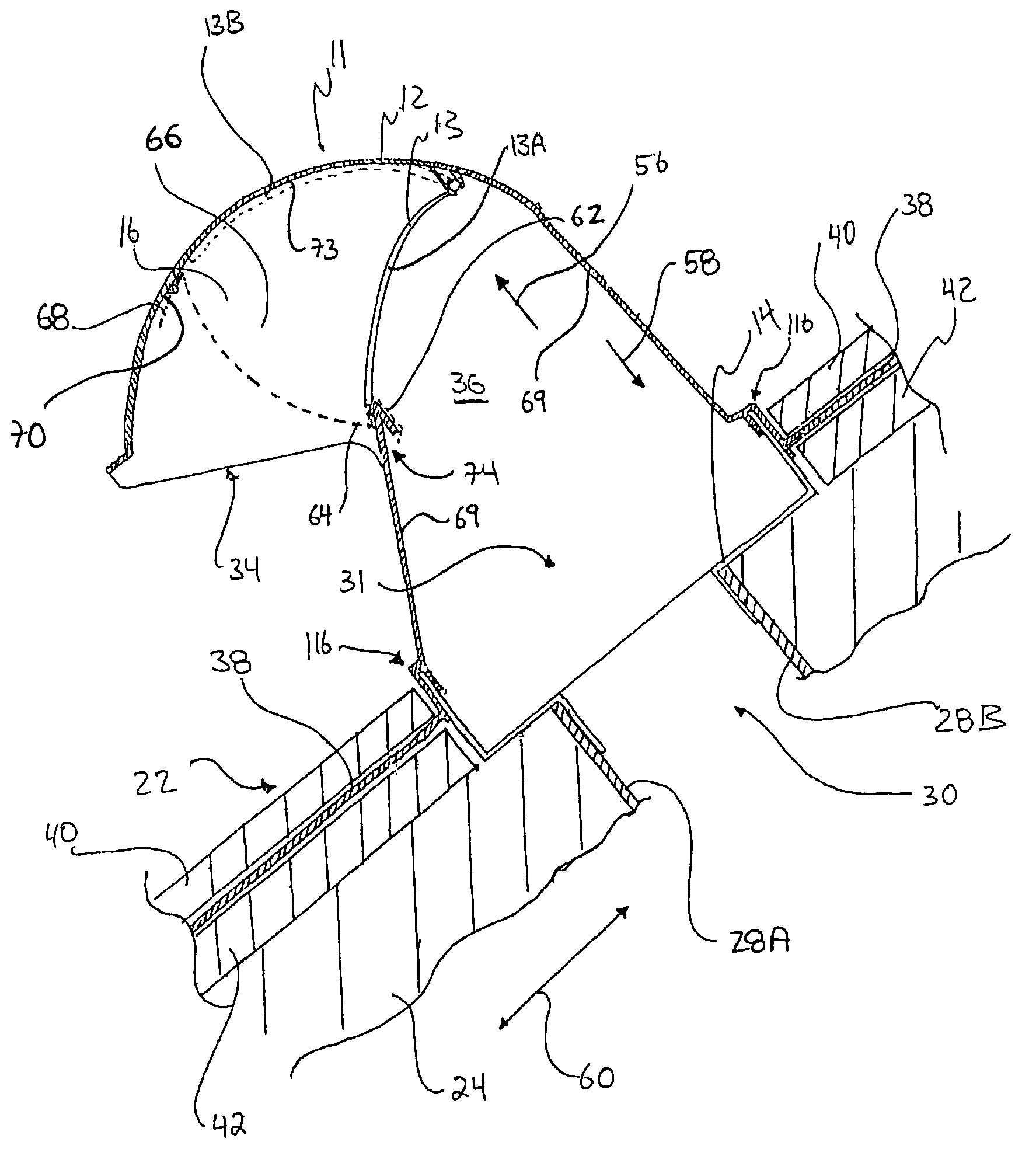
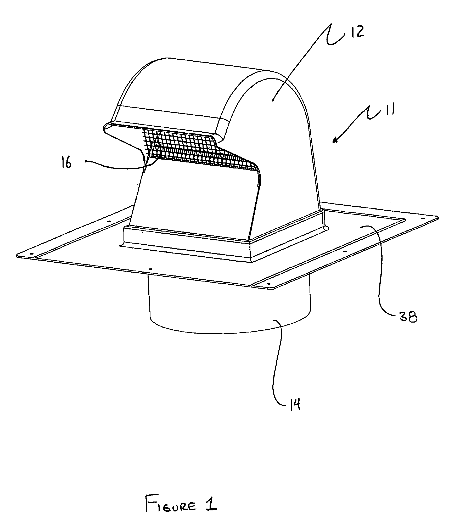
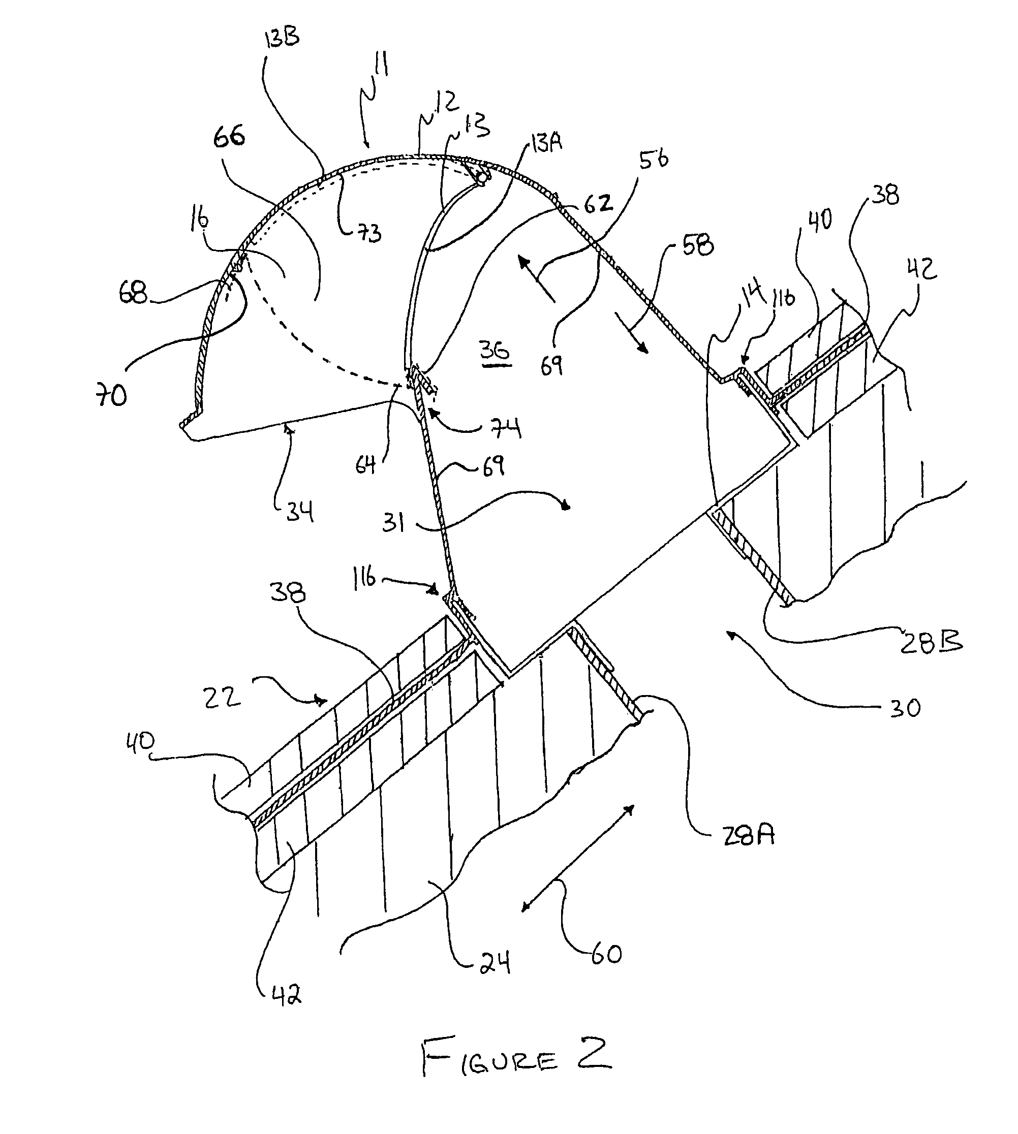
"The invention provides a vent that includes a hollow cover member and a screen. The screen has a bend that receives a protrusion from the cover member, and the screen is resiliently deformable to secure the screen to the cover member and spanning the vent passageway. The screen has multiple surfaces that exert pressure on the protrusion. The vent may also include a damper member located in the vent passageway and pivotally coupled to the cover member. The damper member has a curved profile that matches the curved contour of the cover member surface. The invention also provides a vent that includes a cover member with a first bend and a damper member with a second bend. The technical effects of the invention include improved ventilation, reduced noise, and improved aesthetics."

Problems solved by technology

Some dampers undesirably restrict the flow of gas in the desired direction.
As screens are typically located near the outermost ends of vents, there is a considerable likelihood for a screen to be damaged or to weaken over time because of exposure to the elements.
Replacement of a screen that is attached to a vent component using fasteners requires removing and replacing the fasteners which can damage the body of the vent component.

Method used


Image

  • Vent apparatus
  • Vent apparatus
  • Vent apparatus

Examples


Embodiment Construction

[0038]Throughout the following description, specific details are set forth in order to provide a more thorough understanding of the invention. However, the invention may be practised without these particulars. In other instances, well known elements have not been shown or described in detail to avoid unnecessarily obscuring the invention. Accordingly, the specification and drawings are to be regarded in an illustrative, rather than a restrictive, sense.

[0039]The invention disclosed herein relates to vents which provide a route for the exchange of air or other gases through a building envelope. Typically, a vent is mounted to provide a passageway through the building envelope (i.e. the walls or roof). The interior end of the vent may be coupled to a conduit, which may generally comprise any aperture, duct, passageway, flume, spout, hose, tube, pipe, channel or the like. Typical examples of conduits include, but are not limited to, air ducts for moving air within a building's heating,...


PUM


Abstract

A vent provides a route for gas flow through a building envelope. The vent comprises a substantially hollow cover member having a cover member surface which defines a vent passageway. The vent may comprise a substantially hollow adapter member. The adapter member is coupleable to the cover member at its exterior end and to a conduit at its interior end to provide fluid communication between the vent passageway and the conduit. The vent may comprise a screen which extends across the vent passageway. The screen has a deformable bend and a plurality of surfaces which secure the screen to the cover member without using separate fasteners. The vent may comprise a damper member with an exterior surface having a profile that conforms to the contour of a portion of the cover member surface.

Description

TECHNICAL FIELD[0001]The invention pertains to vents. Particular embodiments of the invention relate to vents used in buildings.BACKGROUND[0002]Many buildings have vents which provide routes for exchange, ventilation, circulation and / or movement of gas through the building envelope. Such gases may comprise air or water vapour, for example. Buildings may have ventilation systems, which take in “fresh” air from outside of the building and expel “stale” air from inside the building. Fresh air may be taken into a building or stale air may be expelled from a building through one or more vents. Some buildings incorporate other systems and / or apparatus, such as air conditioning systems, range hoods and forced air clothes dryers, which require gas flow between the inside and outside of a building.[0003]Typically, a vent is associated with a conduit which conveys gas towards or away from the vent. A vent typically comprises a vent passageway in fluid communication with the associated conduit...

Claims


Application Information

Patent Timeline
Patent Type & Authority Patents(United States)
IPC IPC(8): F24F13/20F24F7/02
CPCF24F7/02
Inventor KOESSLER, JUERGEN
Owner MENZIES ROOFING CORP
Learn More