Coupling for heat transfer member

Inactive Publication Date: 2006-02-07
LG ELECTRONICS INC +1
View PDF12 Cites 32 Cited by
  • Summary
  • Abstract
  • Description
  • Claims
  • Application Information

AI Technical Summary

Benefits of technology

[0019]Accordingly, the present invention is directed to provide a more firmly structured connection between components by allowing a brazing material to be uniformly introduced between, e.g., a transition member and an external heat transfer member and between an adaptor and an external heat transfer member, and by discharging the air bubbles in an air pocket efficiently and easily, and that substantially obviates one or more problems due to limitations and disadvantages of the related art.

Problems solved by technology

Therefore, the brazing strength between the external heat transfer member 18 and the transition member 16, and the brazing strength between the external heat transfer member 18 and the adaptor ring 19 is not uniform, thereby potentially causing problems with the braze.

Method used


Image

  • Coupling for heat transfer member
  • Coupling for heat transfer member
  • Coupling for heat transfer member

Examples


Embodiment Construction

[0043]Reference will now be made in detail to the preferred embodiments of the present invention, examples of which are illustrated in the accompanying drawings.

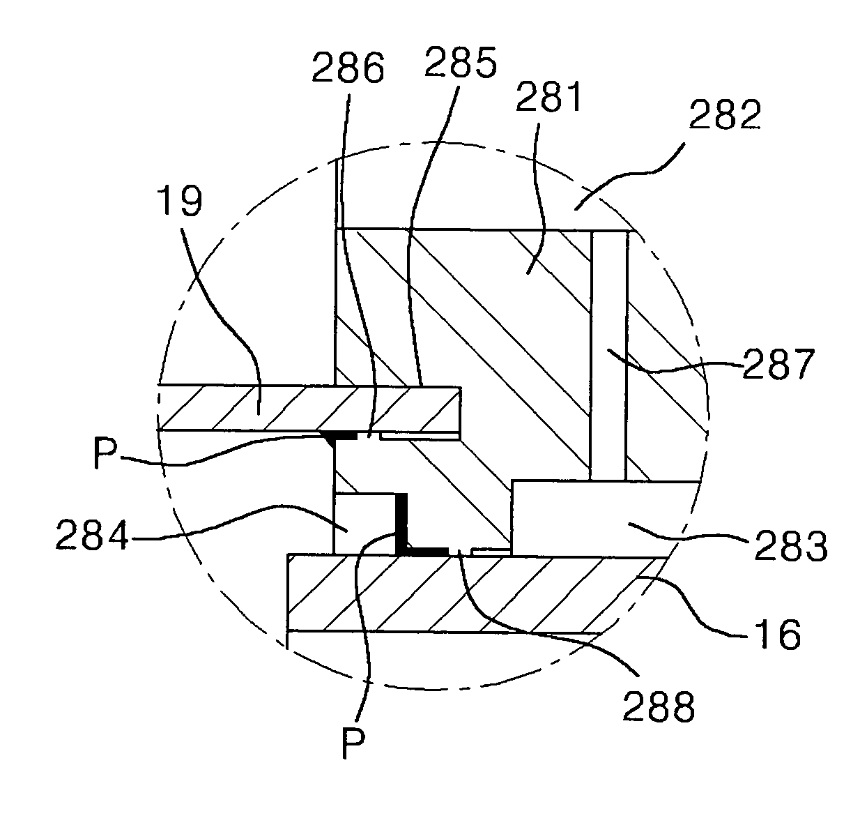
[0044]In order to increase the efficiency of the brazing process, a reciprocating device of the present invention adopts a configuration in which a stepped portion is provided on a predetermined portion of the inner circumferential surface of a base of an external heat transfer member, that is in contact with a transition member, with a predetermined diameter. A blocking protrusion is provided inwardly from the stepped portion. In addition, another blocking protrusion is provided on the base of the external heat transfer member, on a predetermined portion of the surface contacting with an insertion groove into which an adaptor ring is inserted.

[0045]In addition, a vent hole is provided on the external heat transfer member to allow an air pocket to connected to the exterior.

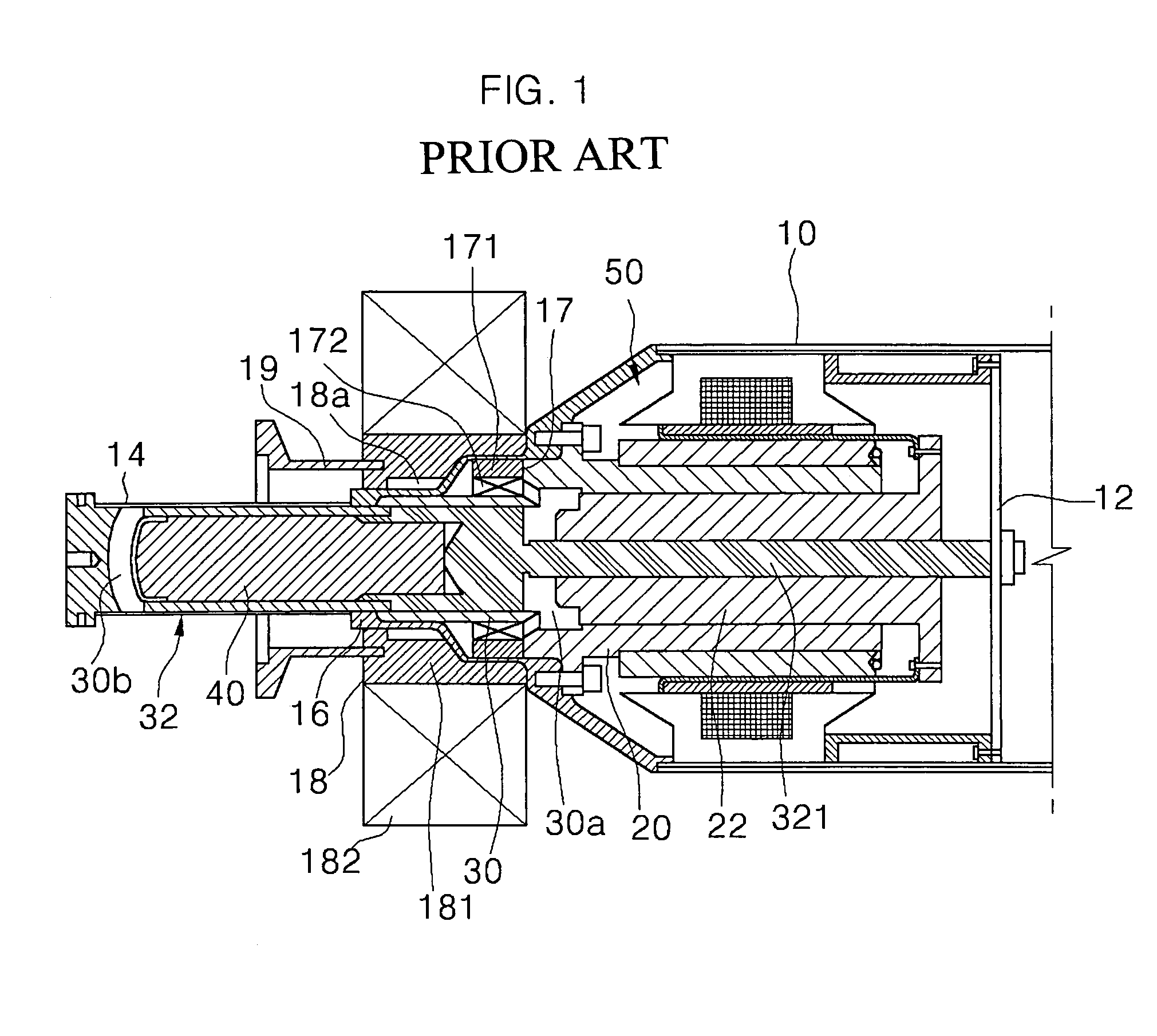
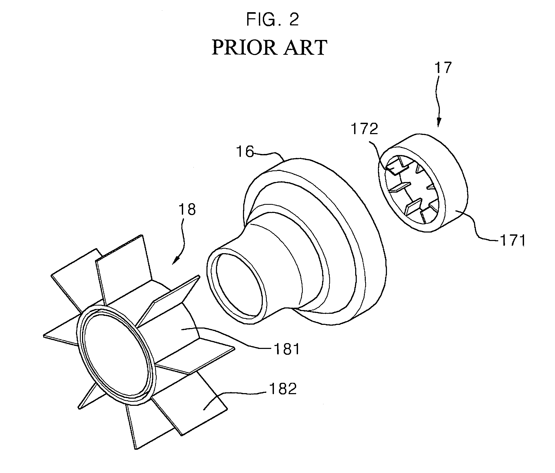
[0046]Hereinafter, an embodiment of the present inve...


PUM

PropertyMeasurementUnit
Areaaaaaaaaaaa
Circumferenceaaaaaaaaaa

Abstract

A heat transfer member having an external heat transfer member including an insertion hole having an adaptor ring inserted thereinto, and at least one of a base blocking protrusion and a grove blocking protrusion formed on a predetermined portion of the surface of the base confronting the inserted adaptor ring inside the insertion groove, for increasing the coupling strength of the external radiating member and the adaptor ring and the transition member.

Description

CROSS-REFERENCE TO RELATED APPLICATION[0001]The present application is related to Korean Paten Application No. 2002-006326, filed on Feb. 4, 2002BACKGROUND OF THE INVENTION[0002]1. Field of the Invention[0003]The present invention relates to a heat transfer member, and more particularly, to an external heat transfer member and a transition member having improved coupling strength.[0004]2. Description of the Related Art[0005]Generally, a variety of reciprocating devices, including but not limited to free-piston machines, are often used in a heat regeneration type of refrigerator, including but not limited to Stirling coolers, Gifford-McMahon refrigerators, and the like.[0006]A conventional free-piston machine is described in U.S. Pat. No. 6,293,184, which issued to Unger on Sep. 25, 2001, the contents of which are expressly incorporated by reference in its entirety. Additionally, hereinafter, the structure and operation of a conventional typical free piston machine is described in FI...

Claims


Application Information

Patent Timeline
IPC IPC(8): F25B9/14F25B9/00B23K1/00
CPCB23K1/0008F25B9/14F25B2309/001B23K2201/04B23K2101/04F25B9/00
Inventor UNGER, REUVENHWANG, DONG GONCHUNG, WOO SUK
Owner LG ELECTRONICS INC
Why Eureka
Try Eureka