
High performance short-wave broadcasting transmitter optimized for digital broadcasting

a short-wave broadcasting and optimized technology, applied in the direction of digital transmission, phase-modulated carrier system, amplifier modification to reduce non-linear distortion, etc., can solve the problem of insufficient operation system, parasite transmission in channel adjacent to the channel used by the transmitter, and the problem of inability to solve the problem of digital type transmission, etc. problem, to achieve the effect of maximizing efficiency, and reducing the global efficiency of the transmitter

Inactive Publication Date: 2006-01-31
THOMSON CSF SA
View PDF22 Cites 3 Cited by
  • Summary
  • Abstract
  • Description
  • Claims
  • Application Information

AI Technical Summary

Benefits of technology

[0023]The concept on which the invention is based is to agree to reduce the global efficiency of the transmitter for low amplitude signals while maximizing efficiency for higher amplitude signals which cause a greater energy consumption.
[0031]The main advantage of the transmitter according to the invention is that it is simple to apply and only modifies the exciter of the power tube of standard transmitters if the power tube is not sufficiently linear.
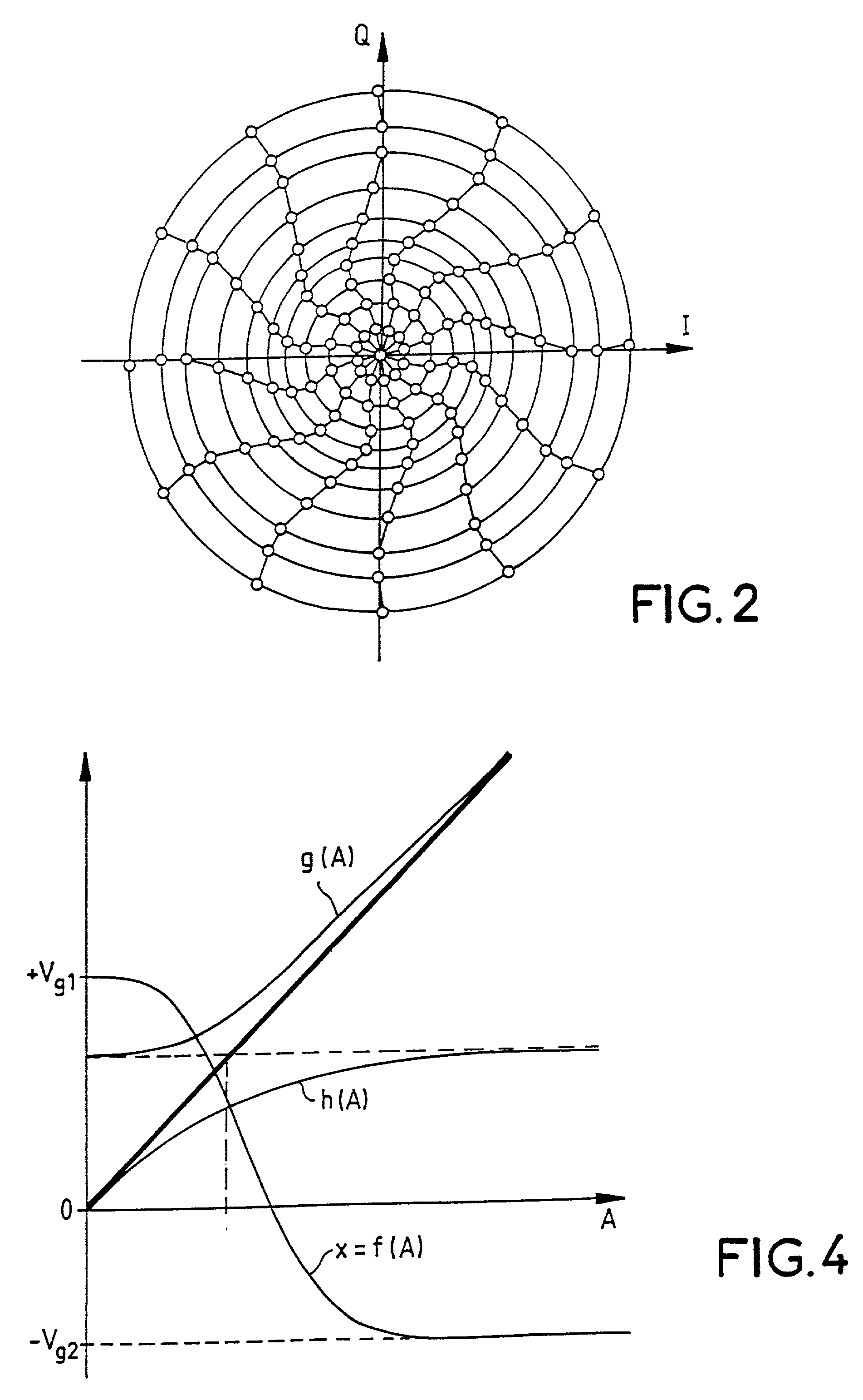
[0032]Another advantage is that it provides a simple solution to the requirement for linearity of the transmitter for low level signals applied to the transmitter input, the operating point of the output tube being displaced such that the amplification of the output tube is linear or quasi-linear.
[0034]Constraints on the passband of the amplitude modulator are lower since the amplitude of the output signal always keeps a minimum determined value and does not have any sharp direction changes widening the pass band.
[0036]Another advantage is that the approximate linearity of the transmission system, both in amplitude and in phase, may easily be corrected after an initial and possibly periodic calibration phase to determine the exact values of the Im(t), Qm(t) and A(t) signals to be sent to the complex exciter input modulator and to the amplitude modulator.

Problems solved by technology

Tests carried out up to now on this type of transmitter show that although the transmitted signal quality can be considered as being sufficient for reception, it is insufficient for an operational system that will need to cohabit with other transmitters, regardless of whether they are amplitude or digital modulation signals.
Even if the precaution of transmitting a carrier residue is taken in order to make operation of transmitter performances linear in terms of distortion, pass band and neutralization, the result is that the parasite transmissions in channels adjacent to the channels used by the transmitter are too high.
Therefore the problem with the transmission of a digital type signal cannot be solved by simply adding control signals on existing transmitters.
Unfortunately, apart from its deplorable efficiency of between 20 and 25% maximum, this system cannot be used for the main reason that there is no power tube within the useable 100 kW class, since the tubes are optimized to operate in class C in which energy efficiency is optimal.
But economically it is not very attractive, since it requires the use of two transmitter output power tubes.

Method used


Image

  • High performance short-wave broadcasting transmitter optimized for digital broadcasting
  • High performance short-wave broadcasting transmitter optimized for digital broadcasting
  • High performance short-wave broadcasting transmitter optimized for digital broadcasting

Examples


Embodiment Construction

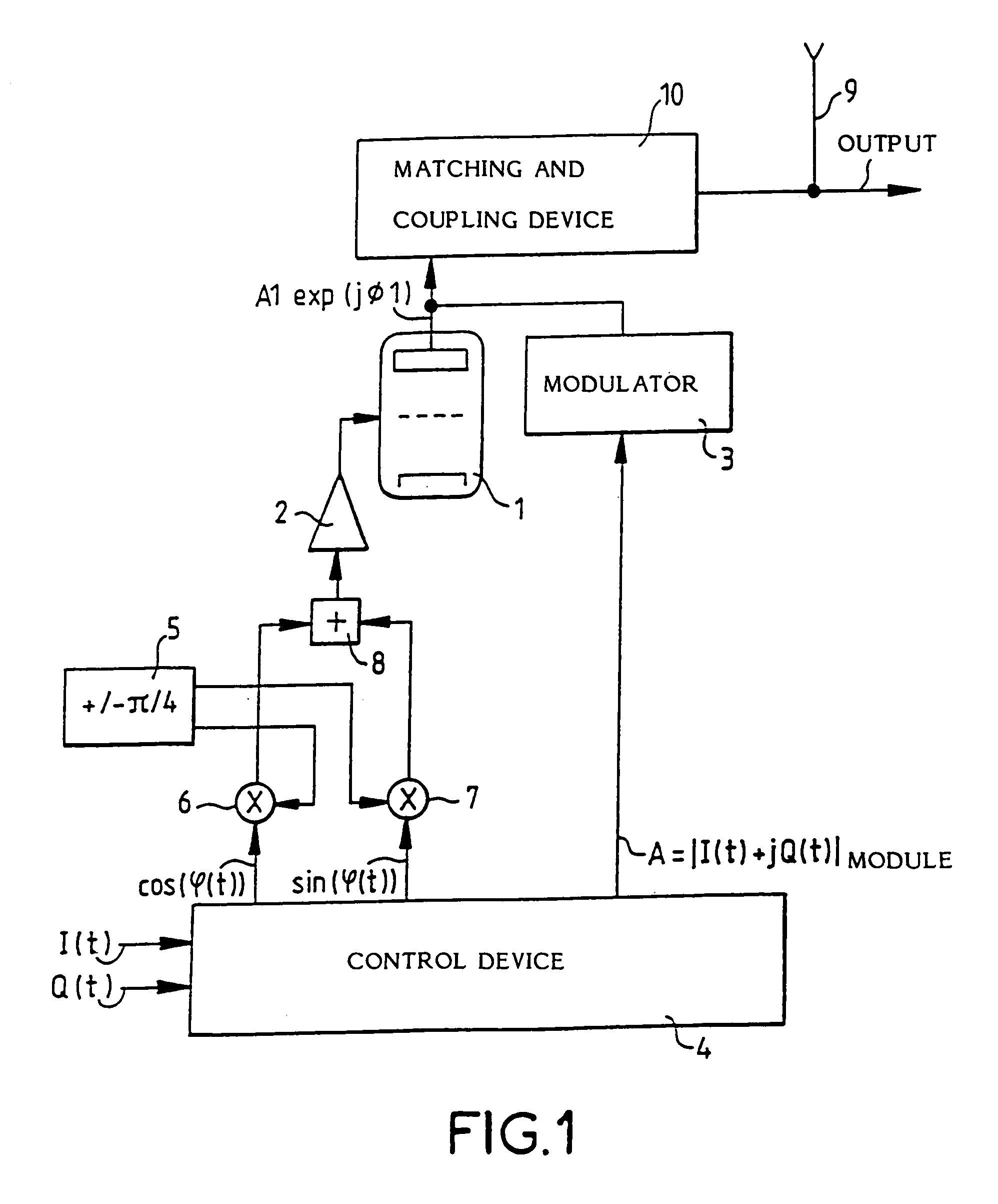
[0044]The transmitter shown in FIG. 1 comprises a power tube 1, the grid of which is excited by an excitation device 2, and the anode of which is modulated in amplitude by a modulator 3. A control device 4 generates the signals necessary for phase control of the excitation device 2 and amplitude control of the modulator 3 starting from the real component I(t) and the imaginary component Q(t) of the complex signal to be transmitted.

[0045]Phase modulation of the grid of tube 1 is achieved starting from the sine and cosine of the phase angle φ calculated by the conversion device 4 and applied to the first operand inputs of the multiplier circuits 6 and 7. Second operand inputs of the multiplier circuits 6 and 7 also receive two sinusoidal signals with constant amplitude and with a frequency equal to the frequency supplied by the synthesizer 5, but for which the phases can be shifted by 90° with respect to each other. An adder circuit 8 adds signals obtained at the output from the two m...


PUM


Abstract

A short wave high efficiency radio broadcasting transmitter for digital transmissions. The transmitter includes a power tube in which the grid is excited by a variable phase signal through an excitation device and in which the anode is amplitude modulated by the output signal from a modulator. The phase and amplitude signals applied to the grid and anode of the tube respectively represent the phase and amplitude of the complex signal to be transmitted. The amplification characteristic of the excitation device remains linear for low amplitudes of the signal to be transmitted and operates under saturated conditions when the amplitude of the signal to be transmitted exceeds a given threshold value, so that the amplification characteristic of the transmitter as a whole remains linear independently of the amplitude of the signal to be transmitted. Such a transmitter may find particular application as a short wave transmitter.

Description

CROSS-REFERENCE TO RELATED APPLICATIONS[0001]This application claims priority under 35 U.S.C. 119 and the international convention to French application no. 99 00240, filed Jan. 12, 1999.STATEMENT REGARDING FEDERALLY SPONSORED RESEARCH OR DEVELOPMENT[0002]Not applicable.THE NAMES OF THE PARTIES TO A JOINT RESEARCH AGREEMENT[0003]Not applicable.INCORPORATION-BY-REFERENCE OF MATERIAL SUBMITTED ON A COMPACT DISK[0004]Not applicable.BACKGROUND OF THE INVENTION[0005]1. Field of the Invention[0006]This invention relates to a high efficiency radio-broadcasting transmitter optimized for digital type transmissions. It is applicable particularly to short wave radio broadcasting transmissions.[0007]2. Description of Related Art[0008]Radio broadcasting transmitters used at the present time for short wave transmissions are optimized to have a very high efficiency during transmission in pure amplitude modulation with carrier residue.[0009]In order to achieve this, they are organized around a high...

Claims


Application Information

Patent Timeline
IPC IPC(8): H04L27/04H04L27/20H03F1/32H03F1/33H03F3/24H04B1/04
CPCH03F1/3247H03F3/24H03F1/33H04B2001/0408
Inventor LAURENT, PIERRE-ANDRE
Owner THOMSON CSF SA
Learn More