
Light-emitting device and process for its production

a technology of light-emitting devices and production processes, which is applied in the manufacture of electric discharge tubes/lamps, discharge tubes luminescnet screens, other chemical processes, etc., can solve the problems of high energy consumption, long operation time, and low white color of flat fluorescent screens which are airtightly sealed by means of low melting point glass. , to achieve the effect of reducing energy consumption or the operation time, saving energy and cos

Inactive Publication Date: 2006-01-31
ASAHI GLASS CO LTD
View PDF20 Cites 8 Cited by
  • Summary
  • Abstract
  • Description
  • Claims
  • Application Information

AI Technical Summary

Benefits of technology

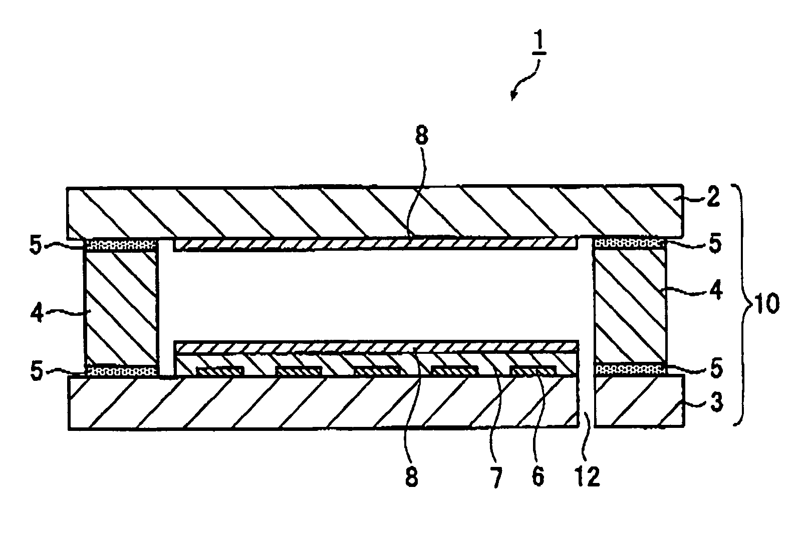
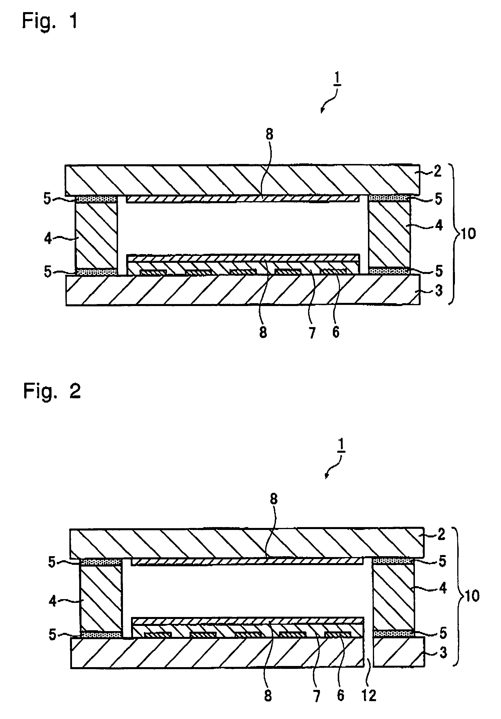
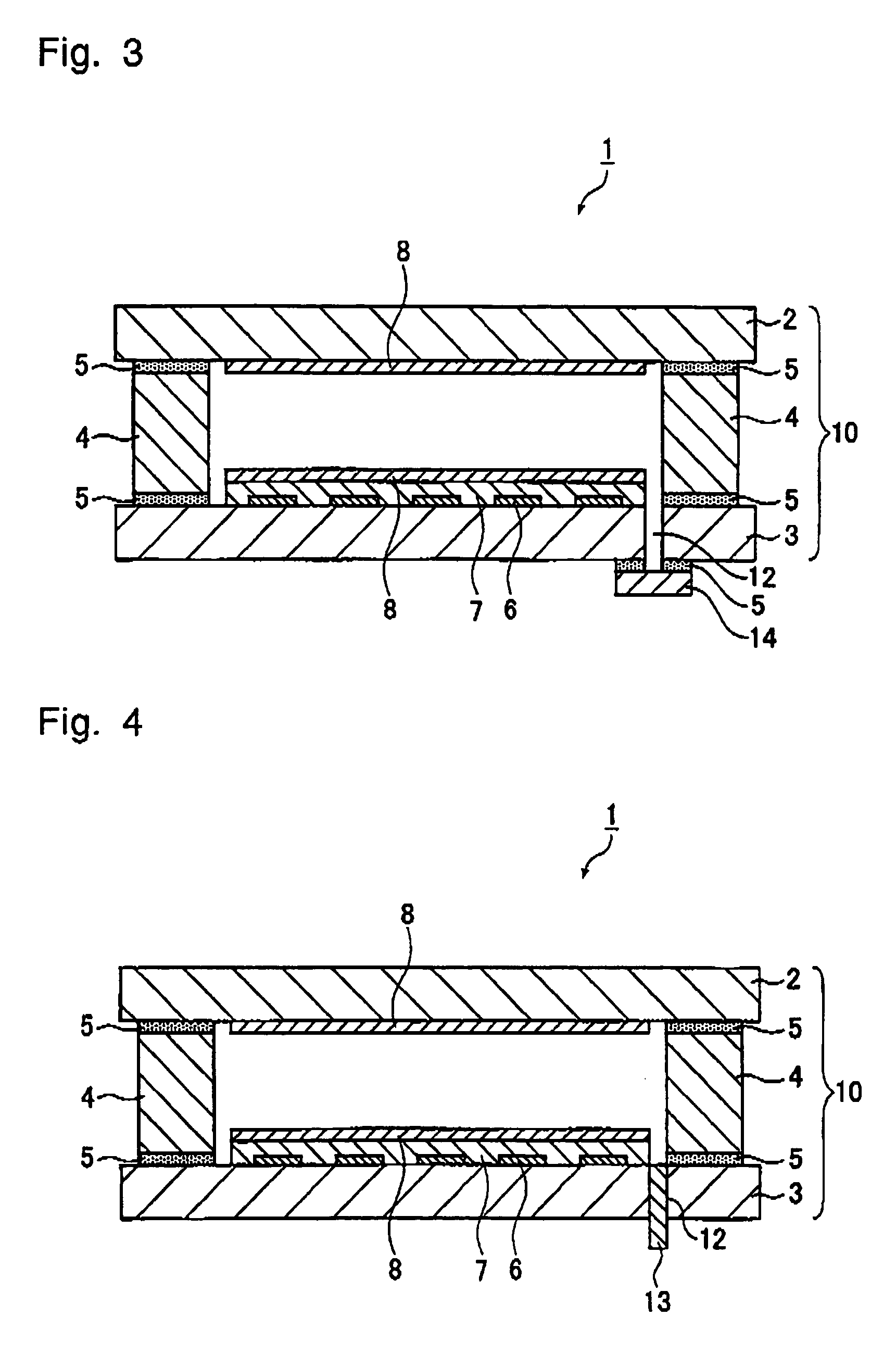
The present invention provides a light-emitting device with an airtight container sealed at a lower temperature using a sealing material that does not contain harmful components such as lead. The sealing material used in the device is a curable methylphenyl silicone resin and a refractory filler, which reduces heat deterioration of the phosphor and improves the color temperature. The sealing is carried out at a lower temperature than using conventional lead-containing glass sealing material, resulting in energy savings and cost reduction. The light-emitting device can be used in various applications such as flat plate type light-emitting devices, outdoor or indoor lighting, or reading light sources.

Problems solved by technology

The color temperature of white color of the flat fluorescent screen which is airtightly sealed by means of a lead-containing low melting point glass, tends to be low due to deterioration of the phosphor by heat.
Further, the conventional sealing step includes a heating step at a temperature of from 400 to 550° C., whereby there is a problem such that the energy consumption is high, or the operation time is long, leading to a high cost.
As a sealing material not containing a hazardous component such as lead or the like, a material such as phosphate glass is available, but such a material has a problem that the bond strength at the sealed portion is weak.

Method used


Image

  • Light-emitting device and process for its production
  • Light-emitting device and process for its production
  • Light-emitting device and process for its production

Examples


example 1

[0098]Into a container equipped with a stirrer, 40 parts by mass (mass excluding the solvent) of a varnish containing a curable methylphenyl silicone resin having the characteristics shown in Table 1 [molar ratio of bifunctional silicon units (=bifunctional silicon units / (sum of bifunctional silicon units and trifunctional silicon unit)), mols of phenyl groups / mols of methyl groups], and 60 parts by mass of spherical silica having an average particle diameter of 3 μm, were put, heated to from 120 to 140° C. and stirred to remove the solvent. Then, the mixture was stepwisely heated to from 150 to 180° C., and the curable methylphenyl silicone resin was partially polymerized until the viscosity of the composition at 180° C. became 20,000 cp. For the measurement of the viscosity, B-type viscometer was used.

[0099]Then, the obtained solid-form sealing composition and a solvent (ethyl acetate) were mixed in a ratio shown in Table 1 to obtain a paste-form sealing composition.

[0100]In Table...

example 2

[0125]A sealing composition was prepared in the same manner as in Example 1 except that a spherical filler having an average particle diameter of 1 μm was used, and evaluation of the obtained sealing composition was carried out. The results are shown in Table 1.

example 3

[0126]Evaluation was carried out by using a sealing composition prepared in the same manner as in Example 1 except that evaluation of properties of the light-emitting device was not carried out. However, in Example 3, the sealing composition was partially polymerized in the same manner as in Example 1 and then molded into a desired shape by casting into a mold made of a fluororesin, and the sealing composition was used in the form of the molded product.


PUM

PropertyMeasurementUnit
particle diameteraaaaaaaaaa
average particle diameteraaaaaaaaaa
molar ratioaaaaaaaaaa

Abstract

To provide a light-emitting device having an airtight container sealed at a lower temperature by means of a sealing material not containing a harmful component such as lead, which is free from heat deterioration of a phosphor, particularly a blue-emitting phosphor.A light-emitting device having an airtight container sealed by means of a sealing composition comprising a curable methylphenyl silicone resin and a refractory filler, wherein the amount of the refractory filler based on the sum of the methylphenyl silicone resin and the refractory filler in the sealing composition, is from 10 to 80 mass %, and the methylphenyl silicone resin has a molar ratio of phenyl groups to methyl groups (i.e. mols of phenyl groups / mols of methyl groups) of from 0.1 to 1.2.

Description

BACKGROUND OF THE INVENTION[0001]1. Field of the Invention[0002]The present invention relates to a light-emitting device, more particularly, to a flat plate type light-emitting device such as a flat fluorescent screen to be used, for example, as a backlight for a liquid crystal display device, and a process for its production.[0003]2. Discussion of Background[0004]As a light-emitting device employing an airtight container, a flat fluorescent screen, fluorescent tube or plasma display panel (PDP) employing gas discharge, a cathode ray tube (CRT) utilizing electron beam, a vacuum fluorescent display (VFD), a field emission display (FED) an electroluminescent display (EL) including organic EL, or an electric lamp employing emission by heating, is, for example, known. One having a single display dot is called a single tube, and one having plural display dots is called a multi tube. For a flat fluorescent screen to be used as e.g. a backlight for a liquid crystal display device, in order...

Claims


Application Information

Patent Timeline
Patent Type & Authority Patents(United States)
IPC IPC(8): H01J61/30H01J29/10C03C27/10C09K3/10H01J5/20H01J9/26H01J61/35H01J61/36H01J65/04
CPCH01J9/266H01J65/046H01J61/361H01J61/35
Inventor ISHIDA, MIZUHO
Owner ASAHI GLASS CO LTD
Learn More