
Oil lamp

a technology of oil lamps and lampshades, which is applied in the direction of capillary burners, combustion types, stoves or ranges, etc., can solve the problems of poor heat conductors, porous materials, and deficient current configurations in some respects, and achieve the effect of enhancing capillary action

Inactive Publication Date: 2006-01-31
LUMETIQUE
View PDF22 Cites 28 Cited by
  • Summary
  • Abstract
  • Description
  • Claims
  • Application Information

AI Technical Summary

Benefits of technology

[0006]The present invention provides an oil lamp having a unique flame formation usable in a variety of decorative applications. The lamp includes a body that has an open upper end and that defines a chamber for carrying a combustible liquid. The lamp further includes a planar wick having a lower end located in the chamber of the body, for contacting the combustible liquid, and an upper end projecting upwardly from the open upper end. The wick may be positioned between first and second plates arranged in a spaced, confronting relationship to enhance capillary action and, when lit, the lamp provides a unique flame formation. Optionally, the lamp may include scented oil to promote the release of fragrance upon heating and the wick can be configured free of material having a high heat conductivity.

Problems solved by technology

Although such lamps have been generally effective, current configurations are deficient in some respects.
For example, the teardrop flame resulting from the wick's rope-like configuration can produce undesirable shadowing and otherwise limit decorative appeal.
In addition, the release of fragrance in traditional lamps is tied to the wick's ability to conduct heat to the reservoir of scented oil; however, materials that promote capillary action, i.e., porous material, often are poor heat conductors.
Thus, the release of fragrance is not optimal.

Method used


Image

  • Oil lamp
  • Oil lamp
  • Oil lamp

Examples


Embodiment Construction

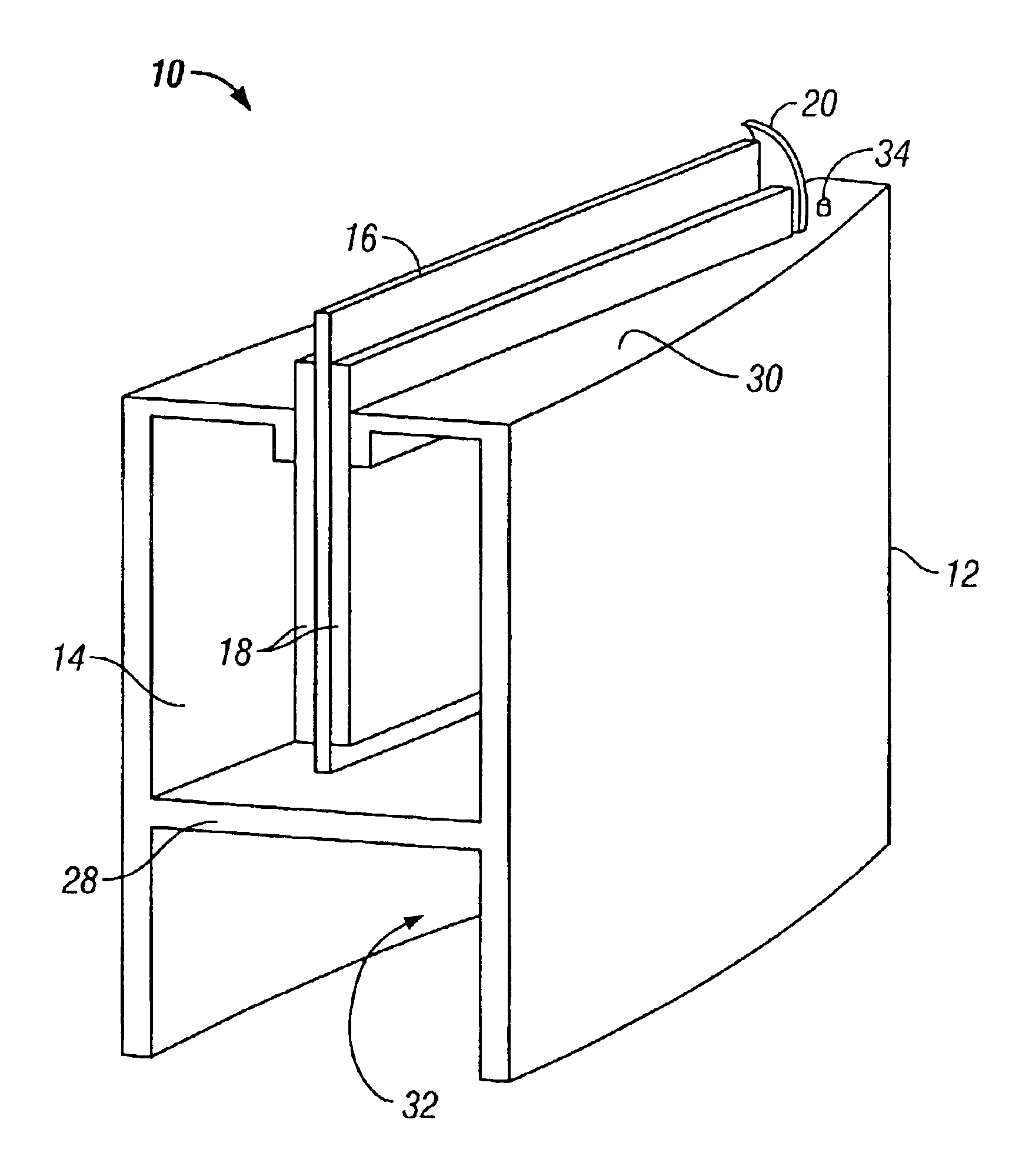
[0021]With reference to the illustrative drawings, and particularly to FIG. 1, there is shown a lamp 10 having a body 12 that defines a chamber 14 to hold a combustible liquid and having a planar wick 16. For purposes of this disclosure, the term lamp refers to a device that is configured to illuminate. The lamp includes two plates 18 extending into the chamber and configured to secure and press the wick, to promote capillary action of the liquid up the wick. When lit, the lamp provides a unique flame formation usable in a variety of decorative applications. The body further includes conductive elements, clips 20 (only one of which is shown), configured to secure the plates and conduct heat from the flame into the reservoir of liquid that, when used with scented oil, promote the release of fragrance. Moreover, the present invention makes it unnecessary to configure the wick with enhanced heat conductivity.

[0022]With reference to FIG. 2, the clips 20 (only one of which is shown) are ...


PUM


Abstract

An oil lamp for providing a unique flame formation usable in a variety of decorative applications. The lamp includes a body that has an open upper end and that defines a chamber for carrying a combustible liquid. The lamp further includes a planar wick having a lower end located in the chamber of the body, for contacting the combustible liquid, and an upper end projecting upwardly from the open upper end. The wick may be positioned between first and second plates arranged in a spaced, confronting relationship to enhance capillary action or may be wrapped about a rigid plate. When lit, the lamp provides a unique flame formation. Optionally, the lamp may include scented oil and a conductive element to promote the release of fragrance upon heating, and the wick can be configured free of material having a high heat conductivity.

Description

[0001]This application claims the benefit of U.S. Provisional Application No. 60 / 331,904, filed Nov. 19, 2001.BACKGROUND OF THE INVENTION[0002]The present invention relates generally to devices of illuminating and, more particularly, to oil lamps.[0003]Oil lamps have long been used for decorative illumination and aromatic purposes. Such lamps typically include a body defining a chamber to hold a reservoir of combustible liquid and a wick to draw up the liquid through capillary action. The wick has an upper end extending out of an opening in the upper portion of the body and a lower end in contact with the reservoir of liquid. For effective capillary action, wicks typically are configured as a cord of fibers, such as cotton threads, braided in a rope-like configuration. When lit, the lamp forms a teardrop flame that is fed by the combustible liquid. Such lamps also may incorporate scented oil for aromatic purposes. Heat generated from the burning of the oil is conducted into the rese...

Claims


Application Information

Patent Timeline
IPC IPC(8): F23D3/24A61L9/03F21V37/00
CPCA61L9/037F23D3/24F21V37/002
Inventor DECKER, DAYNADODSON, STEVEN
Owner LUMETIQUE
Learn More