Transmission chain for use in engine

a technology of transmission chain and transmission shaft, which is applied in the direction of driving chain, chain elements, gearing, etc., can solve the problems of unstable chain path, failure of link plate, and slack generation in the chain, and achieve the effect of stable oil film, significant improvement of chain endurance, and reduction of friction between the chain and the chain guid

Inactive Publication Date: 2009-01-15
TSUBAKIMOTO CHAIN CO
View PDF9 Cites 12 Cited by
  • Summary
  • Abstract
  • Description
  • Claims
  • Application Information

AI Technical Summary

Benefits of technology

[0014]The plate edge configuration produces a capillary action which induces flow of lubricating oil into the lubricating oil-retaining clearance, thereby ensuring formation of a stable oil film, and reduced friction between the chain and a chain guide.
[0015]When the plate flat surfaces come into sliding contact with a flat guide surface of a chain guide lubricating oil retained in the lubricating oil-retaining clearance is reliably sealed, and outward leakage of the lubricating oil is suppressed, so that smooth sliding contact with the chain guide can be maintained. Furthermore, when the transmission has both flat and convex chain guides, since the flat surfaces of the plates come into sliding contact with a flat guide surface and the convex curved surfaces of the plates come into sliding contact with a convex guide surface of the chain guide, concentration of stress from both chain guides at specific positions on the plates is avoided, and the endurance of the chain is significantly improved.
[0016]In a plate of a chain, tensile stress is liable to be concentrated, and fatigue fracture is most likely to occur, at a location on a line intersecting the center of a hole in which a pin or bushing is press-fit and extending to the guide-engaging surface of plate in a direction perpendicular to the direction of elongation of the chain. Because the distance between the boundaries where the flat and convex surfaces of each plate meet is shorter than the chain pitch, the convex curved surface is not formed at the location where stress is liable to be concentrated, and fatigue fracture is most likely to occur. Consequently, reduction in plate strength can be avoided. Stress due to sliding contact with a flat guide surface can act at the location of the above-described line without a significant adverse effect on chain strength, since stress is distributed over two mutually engaging flat surfaces rather than concentrated in a very narrow area.
[0017]Because the distance between the positions at which a plate according to the invention contacts a convex guide surface is less than the corresponding distance in a conventional plate, where the distance is equal to or greater than the chain pitch, sinking of the chain with respect to the convex guide surface is reduced, and chain slack due to sinking of the chain is avoided, so that the chain path is stabilized.
[0018]When the radius curvature of the convex curved surfaces of the plate increases gradually in the direction from the flat surface toward concave surface, excessive widening of the lubricating oil-retaining clearance is avoided, and the capillary action which induces lubricating oil into the lubricating oil-retaining clearance is enhanced. Thus, smoother sliding contact of the plate with a chain guide can be achieved.
[0019]When each plate has substantially identical edge configurations facing the inside of the loop and facing the outside of the loop, the shapes of the plates can be symmetrical about a plane extending along the direction of the length of the chain, and it becomes unnecessary to consider the orientation of the plates when assembling the chain. Thus, the chain assembly operation becomes easier. Moreover, a weight reduction of the plates and an overall reduction in the weight of the chain can be realized.

Problems solved by technology

As shown in FIG. 10, since an inner link plate 510, or the outer link plate 550, comes into contact with a linear chain guide G2 at small contact regions Z, it is not possible to retain sufficient lubricating oil, and sliding resistance is generated in both regions Z, so that there is a possibility of failure of the link plates.
The result is that the chain sinks toward the arc-shaped guide G1, causing slack to be generated in the chain and a possibility for the chain path to become unstable.

Method used


Image

  • Transmission chain for use in engine
  • Transmission chain for use in engine
  • Transmission chain for use in engine

Examples


Embodiment Construction

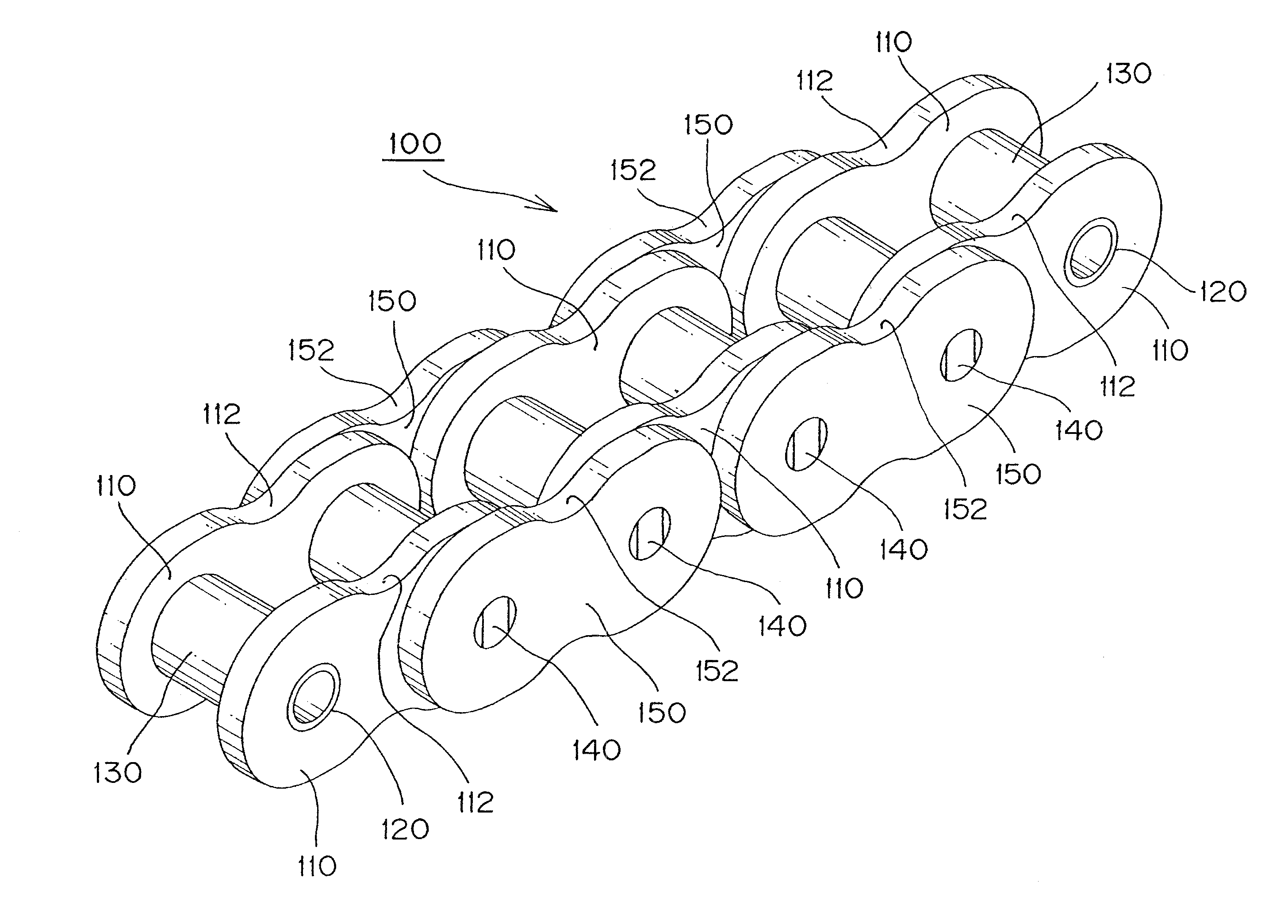
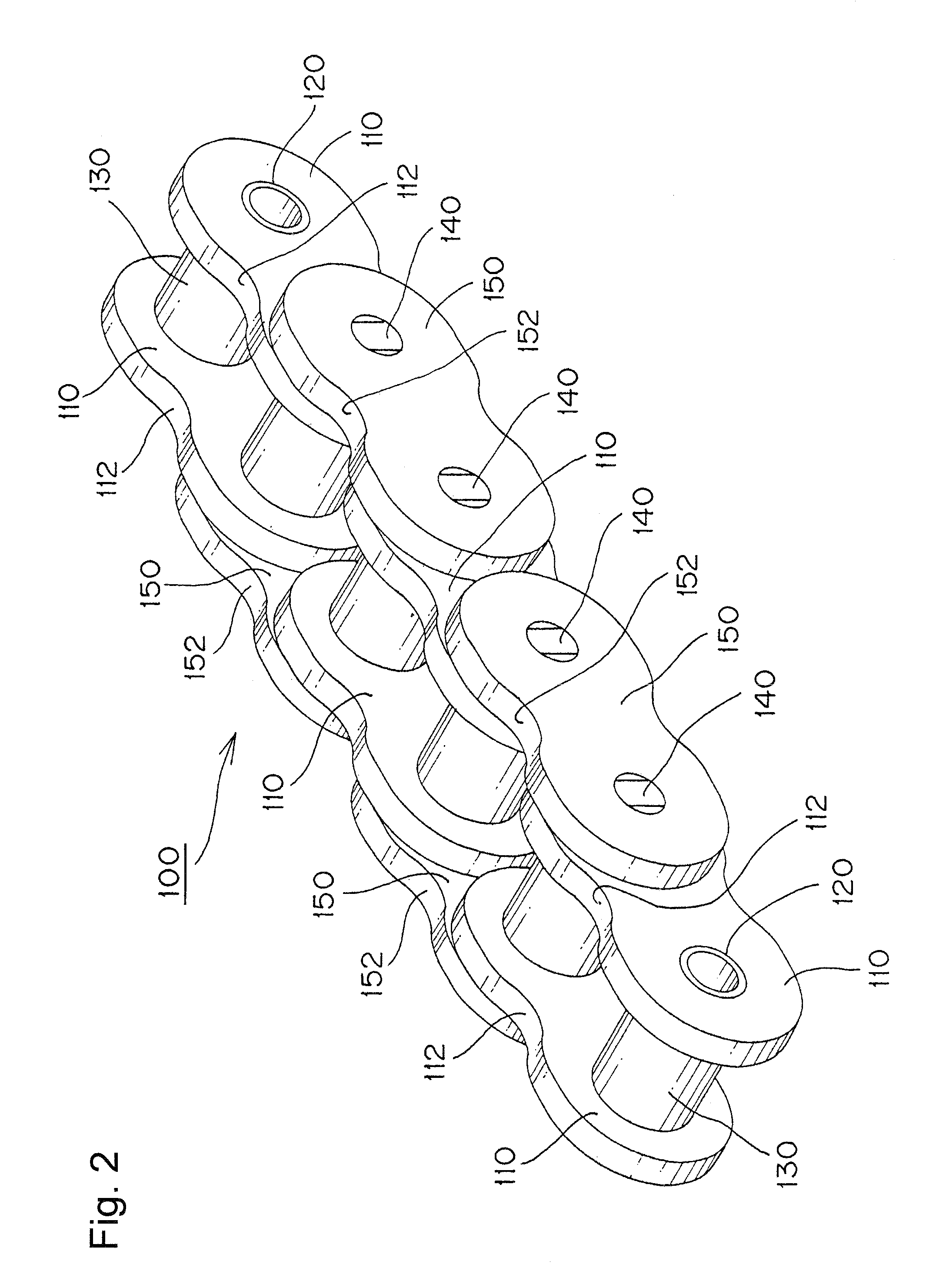
[0030]When the guide-engaging portion of each plate comprises spaced front and rear flat surfaces and front and rear convex curved surfaces, each continuous with one of the flat surfaces, the convex curved surfaces are disposed between the flat surfaces, and a concave surface extends from one of the convex curved surfaces to the other for forming a lubricating oil-retaining clearance, and the distance between the boundaries between the flat and convex surfaces of each plate is shorter than the chain pitch, sinking of the chain toward a convex guide surface of the chain guide is reduced, and the chain path is stabilized. At the same time, the strength of the portions of the plates where stress is liable to be concentrated and fatigue failure is likely to occur is improved, and lubricating oil is more reliably retained between the chain guide and the plate so that superior endurance can be realized.

[0031]The invention can be embodied in various kinds of transmission chains, including ...


PUM


Abstract

The plates of transmission chain for an engine are formed with a guide-contacting configuration composed of spaced flat surfaces that come into sliding contact with a flat chain guide, and convex surfaces, continuous with and between the flat surfaces, for sliding contact with a convex chain guide. The convex surfaces are connected by a concave surface that, with the guide surface, forms an oil-retaining clearance. The radius of curvature of the convex curved surfaces of the plate preferably increases gradually from the location where they meet the flat surfaces toward the location where they meet the concave surface. The plates can have the same configuration on the side facing the inside of chain loop as on the side facing the outside of the chain loop.

Description

CROSS-REFERENCE TO RELATED APPLICATION[0001]This application claims priority on the basis of Japanese patent application 2007-184864, filed Jul. 13, 2007. The disclosure of Japanese application 2007-184864 is incorporated by reference.FIELD OF THE INVENTION[0002]The invention relates to a transmission chain for use in an engine such as an automobile engine, and more specifically to a chain for use as a timing chain for transmitting power to a camshaft, or an auxiliary mechanism such as an oil pump or the like, or as a balancer chain.BACKGROUND OF THE INVENTION[0003]Most automobile engines include a chain transmission which transmits power through an endless chain engaged with a driving sprocket and a driven sprocket. In a typical transmission chain, as exemplified by chain 500 in FIG. 10, concave chain surfaces 511 and 551, that come into facing relationship with a chain guide, are formed respectively on the guide facing sides of inner link plates 510 and outer link plate 550. Lubri...

Claims


Application Information

Patent Timeline
Patent Type & Authority Applications(United States)
IPC IPC(8): F16G13/06
CPCF02B2275/08F16G13/08F16G13/06F16G13/04
Inventor TOHARA, TAKASHIKONISHI, TATSUYA
Owner TSUBAKIMOTO CHAIN CO
Why Eureka
Try Eureka