Surface treatment method, surface treatment apparatus, member subjected to surface treatment, and intermediate member to be subjected to surface treatment

a surface treatment and surface treatment technology, applied in the direction of soldering apparatus, manufacturing tools,auxillary welding devices, etc., can solve the problems of port opening shape change undetected, thermal fatigue tends to occur, etc., to prevent material deformation and void

Inactive Publication Date: 2006-01-31
MAZDA MOTOR CORP
View PDF10 Cites 1 Cited by
  • Summary
  • Abstract
  • Description
  • Claims
  • Application Information

AI Technical Summary

Benefits of technology

[0006]The present invention has been made in view of the above problems, and has as its object to provide a surface treatment method and apparatus which can prevent deformation of the material and a void caused by the deformation, a member subjected to this surface treatment, and an intermediate member to be subjected to this surface treatment.
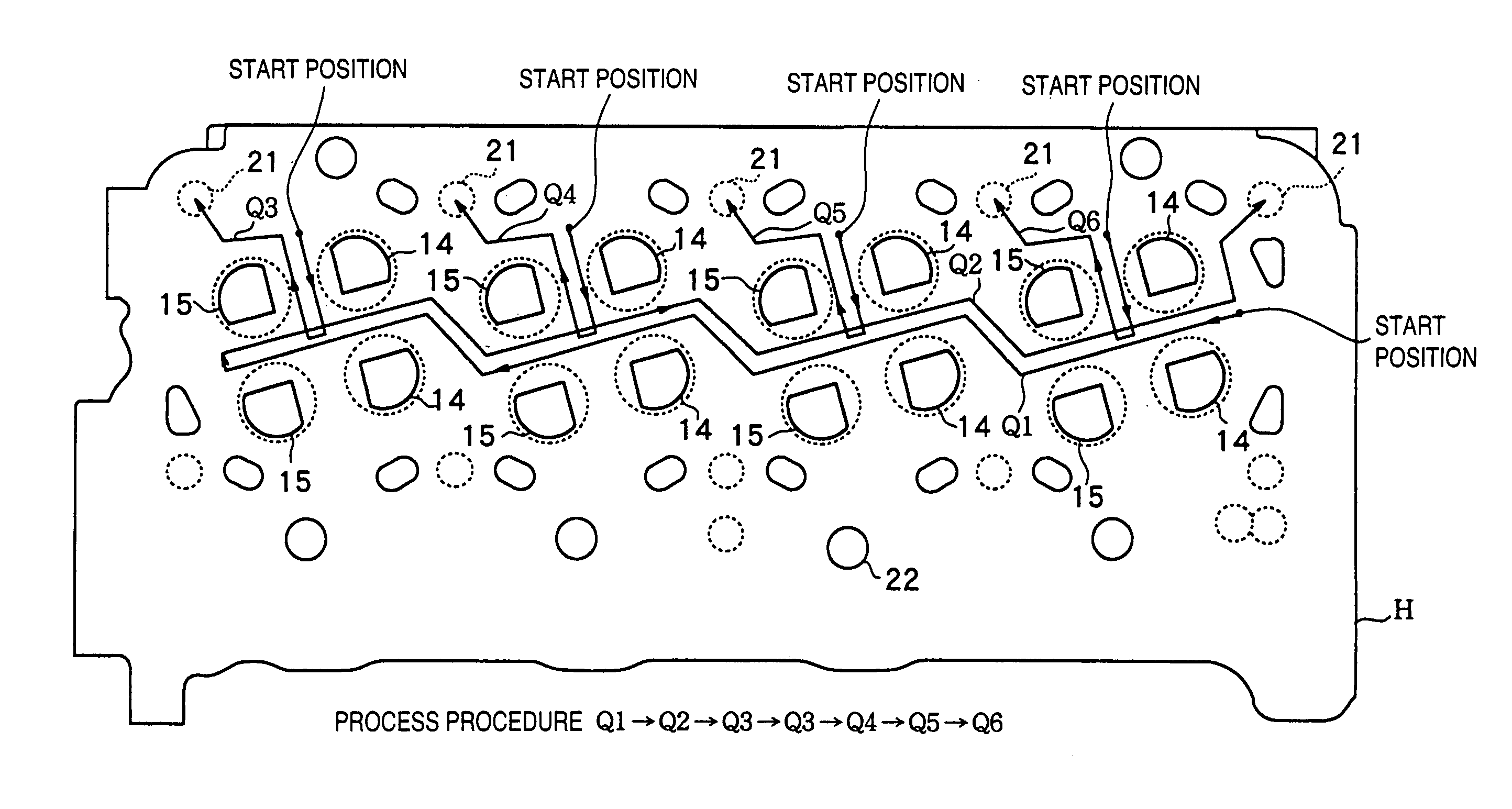
[0007]In order to solve the above problems and to achieve the above object, according to a surface treatment method of the present invention, when a work having a plurality of openings is to be surface-treated in accordance with frictional stirring by inserting a rotary tool in a work surface between the openings, margins for interfering with deformation of the openings due to softening of a material are formed on the openings of the work, the work surface between the openings is stirred by the rotary tool, and post-machining for removing the work surface including the margins is performed. Thus, deformation of the material and a void caused by the deformation can be prevented.
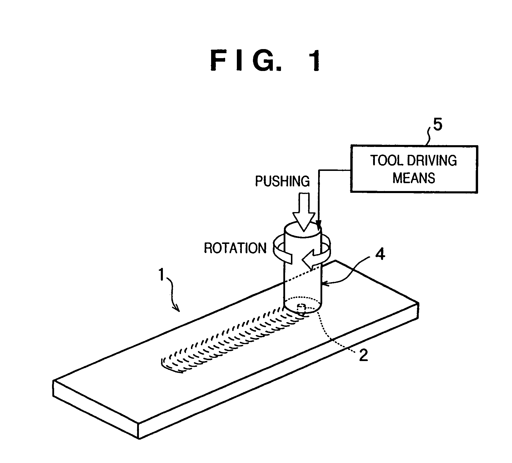
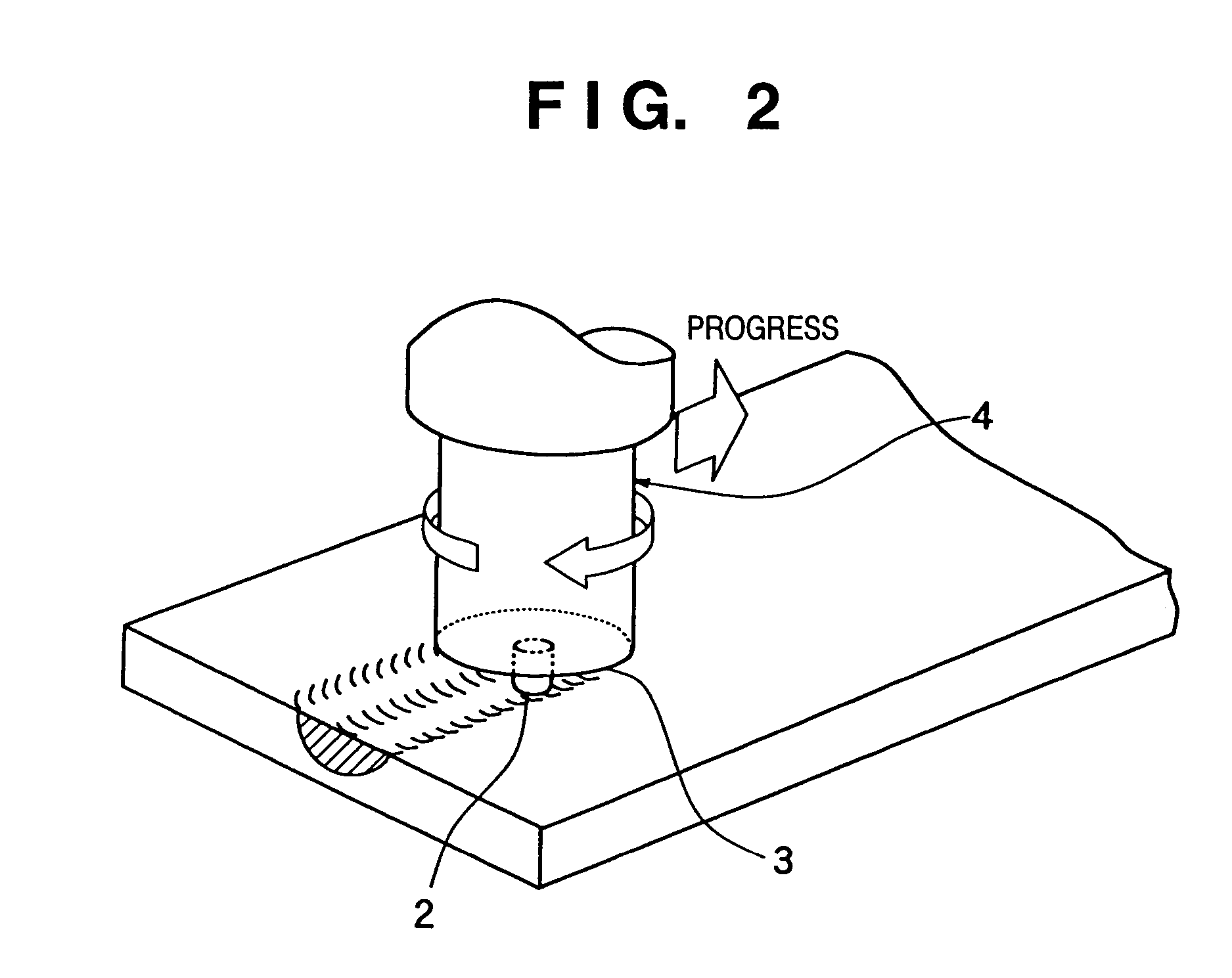
[0008]Preferably, the rotary tool has a rod-like axial portion with a flat distal end, and a projection projecting from the distal end of the axial portion. Thus, the thermal fatigue strength can be improved while preventing deformation of the material and a void caused by the deformation.

Problems solved by technology

A portion between port openings (valve-to-valve portion) of a cylinder head repeats volume expansion due to combustion of the engine and volume shrinkage due to cooling, and cracking caused by thermal fatigue tends to occur there.
The pushing force and rotation moment of the rotary tool plastically deform the matrix structure of the side surfaces of the openings in the vertical and horizontal directions, and accordingly the shapes of the port openings change undesirably.

Method used


Image

  • Surface treatment method, surface treatment apparatus, member subjected to surface treatment, and intermediate member to be subjected to surface treatment
  • Surface treatment method, surface treatment apparatus, member subjected to surface treatment, and intermediate member to be subjected to surface treatment
  • Surface treatment method, surface treatment apparatus, member subjected to surface treatment, and intermediate member to be subjected to surface treatment

Examples


process example

[Other Process Example]

[0114]According to a process example other than surface treatment using the tool changer, the surface temperature of the rotary tool may be measured by using, e.g., a temperature sensor immediately before the start of surface treatment in accordance with frictional stirring, or the thermal expansion amount of the rotary tool may be measured by using, e.g., a touch sensor. The forcing amount of the rotary tool may be corrected in accordance with these measurement values. Alternatively, a plurality of NC control programs may be prepared in advance. Surface treatment may be performed by selecting appropriate NC control programs corresponding to the measurement values in units of works.

[0115]According to this method, even when the rotary tool is thermally expanded by frictional heat, the tool forcing amount can be controlled to be substantially constant. Thus, variations in depth of the surface modification range or occurrence of an internal void can be suppressed...


PUM

PropertyMeasurementUnit
Temperatureaaaaaaaaaa

Abstract

Two beams 17 and 18 perpendicular to a moving trajectory Q are formed in an intake port opening 14 of a cylinder head material to serve as margins for interfering with deformation of the opening 14 due to softening of the material, thereby a deformation of the material and a void caused by the deformation can be prevented in the frictional stirring with the rotary tool.

Description

TECHNICAL FIELD[0001]The present invention relates to a surface treatment method and apparatus for, e.g., an aluminum alloy cast material, a member subjected to this surface treatment, and an intermediate member to be subjected to this surface treatment.BACKGROUND ART[0002]Japanese Patent Laid-Open No. 10-183316 discloses a surface treatment method, in surface treatment for a casting material such as a mating surface with respect to the cylinder block of a cylinder head, of forcing, while rotating, a rotary tool having a projection formed at its distal-end shoulder, thereby stirring in a nonmelted state with heat.[0003]A portion between port openings (valve-to-valve portion) of a cylinder head repeats volume expansion due to combustion of the engine and volume shrinkage due to cooling, and cracking caused by thermal fatigue tends to occur there. Therefore, the valve-to-valve portion is surface-treated by frictional stirring to realize a metal with a finer structure and to decrease t...

Claims


Application Information

Patent Timeline
IPC IPC(8): B23K31/02F02F1/24B22D29/00B23K20/12
CPCB23K20/1215B23K20/1275B23K20/122B23K20/12
Inventor KUSUNOKI, HIROAKIMASUDA, TSUTOMUTOMIYA, KOJI
Owner MAZDA MOTOR CORP
Why Eureka
Try Eureka