
Engine air amount prediction based on engine position

a technology of engine air amount and position prediction, which is applied in the direction of electric control, charge feed system, fuel injection apparatus, etc., can solve the problems of evacuation of intake manifolds and corresponding changes in engine air amount, and achieve accurate prediction of engine air amount during star

Inactive Publication Date: 2006-01-31
FORD GLOBAL TECH LLC
View PDF47 Cites 2 Cited by
  • Summary
  • Abstract
  • Description
  • Claims
  • Application Information

AI Technical Summary

Benefits of technology

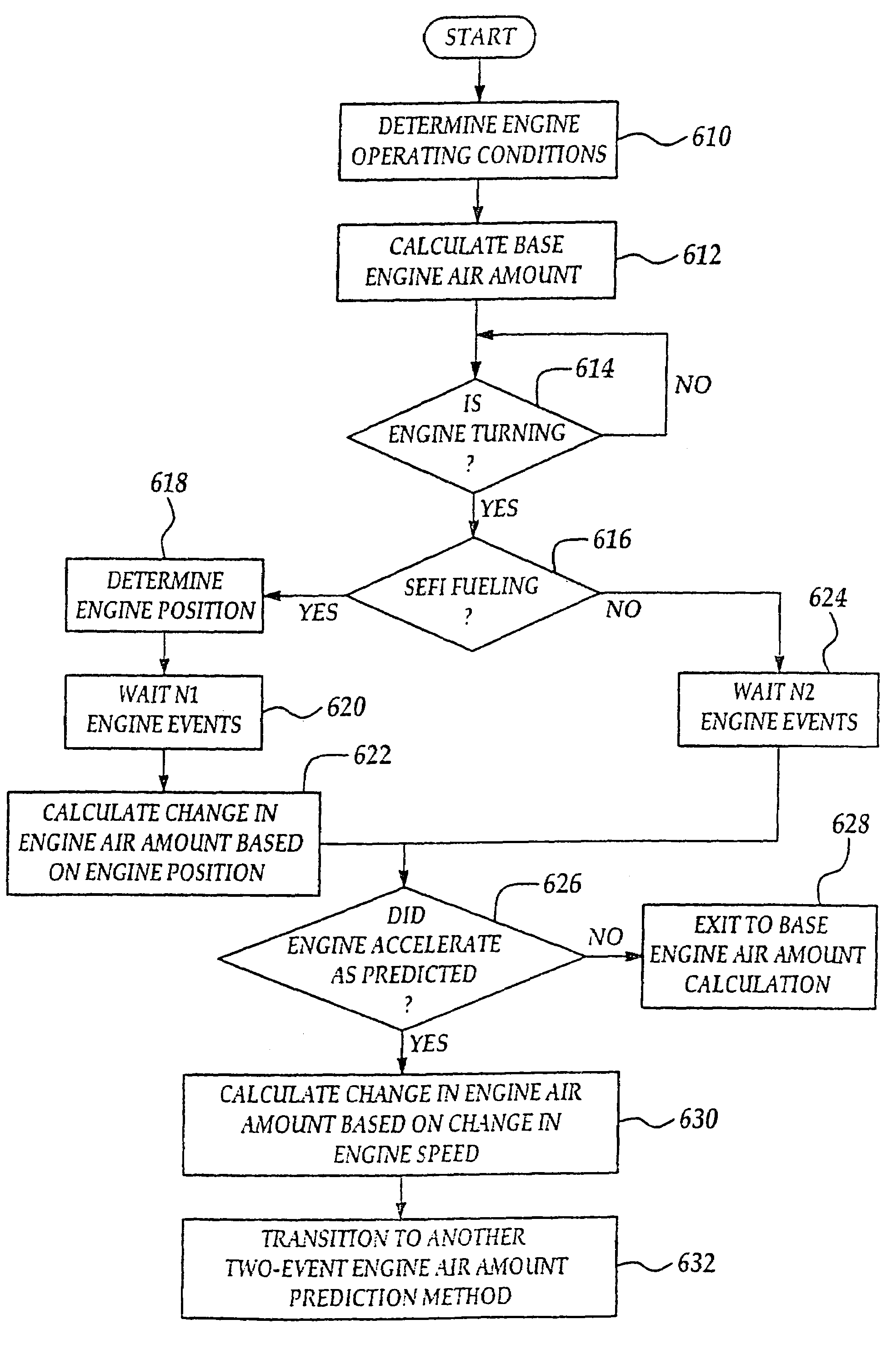
[0006]In accordance with the present invention a method that accurately predicts an engine air amount during start is presented. The method comprises: counting a number of cylinders receiving at least one fuel injection from a start of an operation of the internal combustion engine; and calculating an estimated engine air quantity based on said counted number of cylinders, and adjusting delivered fuel based on said estimated engine air quantity. This method can be used to reduce the above-mentioned limitations of the prior art approaches.
[0007]By estimating an engine air quantity based on a number of cylinders receiving at least one fuel injection, it is possible to accurately determine the amount of air in the engine and thereby provide an appropriate quantity of fuel, even as the air is changing during a start.
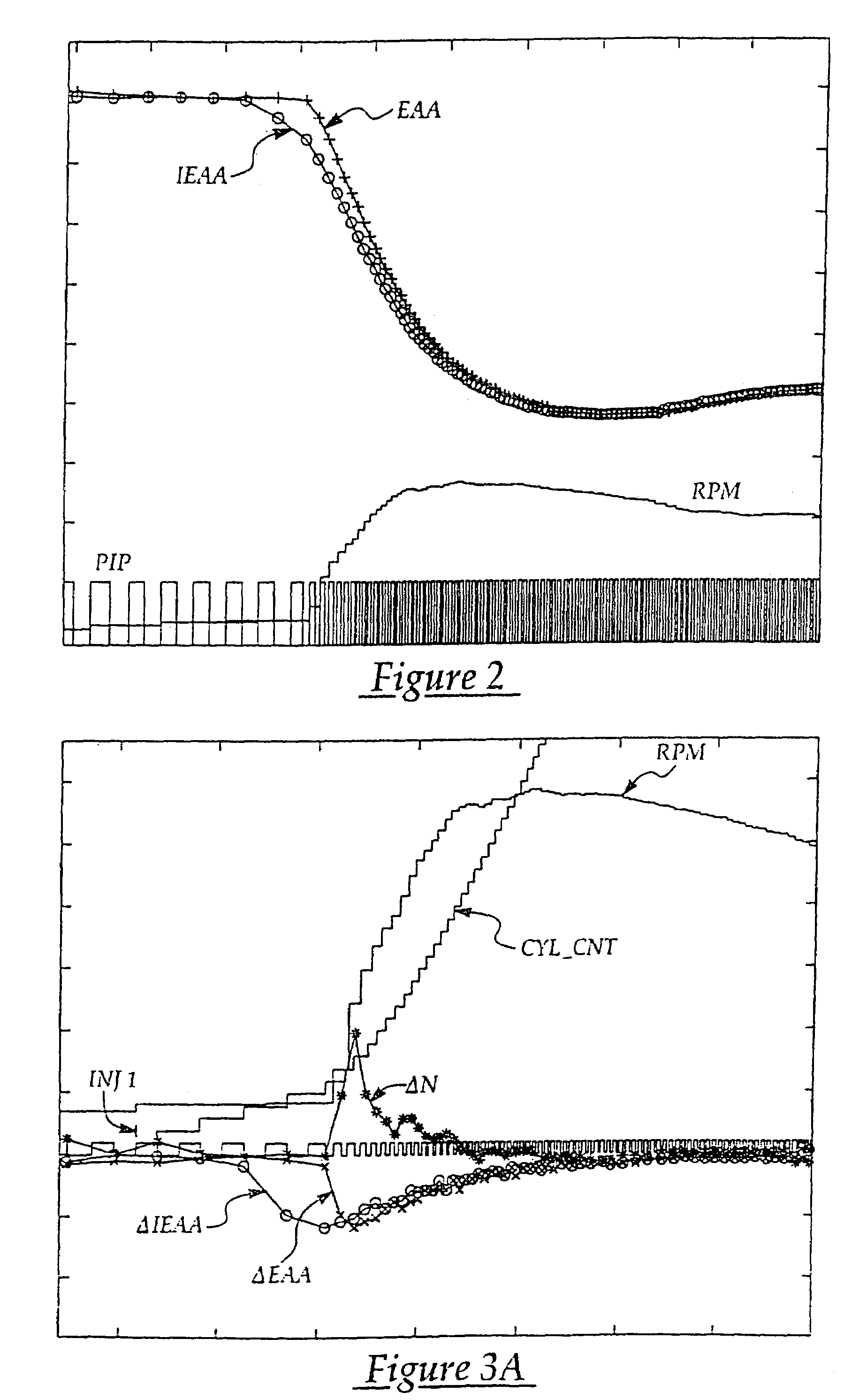
[0008]In other words, from the first cylinder to receive fuel and the number of cylinder firings per revolution it is possible to predict when the first fueled cylinder and subsequent cylinders will fire. During a start, the fired cylinders produce a large engine acceleration. The acceleration in turn increases the piston speed of other cylinders in the engine. For cylinders on their intake stroke, inducting air, the acceleration increases the rate of pressure drop in the cylinder. This causes increased flow from the intake manifold into the cylinder during induction, resulting in evacuation of the intake manifold and a corresponding change in engine air amount. Therefore, by keeping track of the number of fuel injections, the corresponding change in engine air amount can be predicted. Also, given similar starting conditions such as barometric pressure, air temperature, and engine temperature, an engine will fire and induct air in a consistent manor. Consequently, engine air quantity measurements from past starts can be used to accurately predict future engine air amounts, and therefore factors such as engine wear can be taken into account.
[0010]The present invention provides the advantage of improved air / fuel control during engine starting, resulting in lower emissions. This advantage is especially advantageous when a catalyst is cold and its efficiency is low.

Problems solved by technology

This causes increased flow from the intake manifold into the cylinder during induction, resulting in evacuation of the intake manifold and a corresponding change in engine air amount.

Method used


Image

  • Engine air amount prediction based on engine position
  • Engine air amount prediction based on engine position
  • Engine air amount prediction based on engine position

Examples


Embodiment Construction

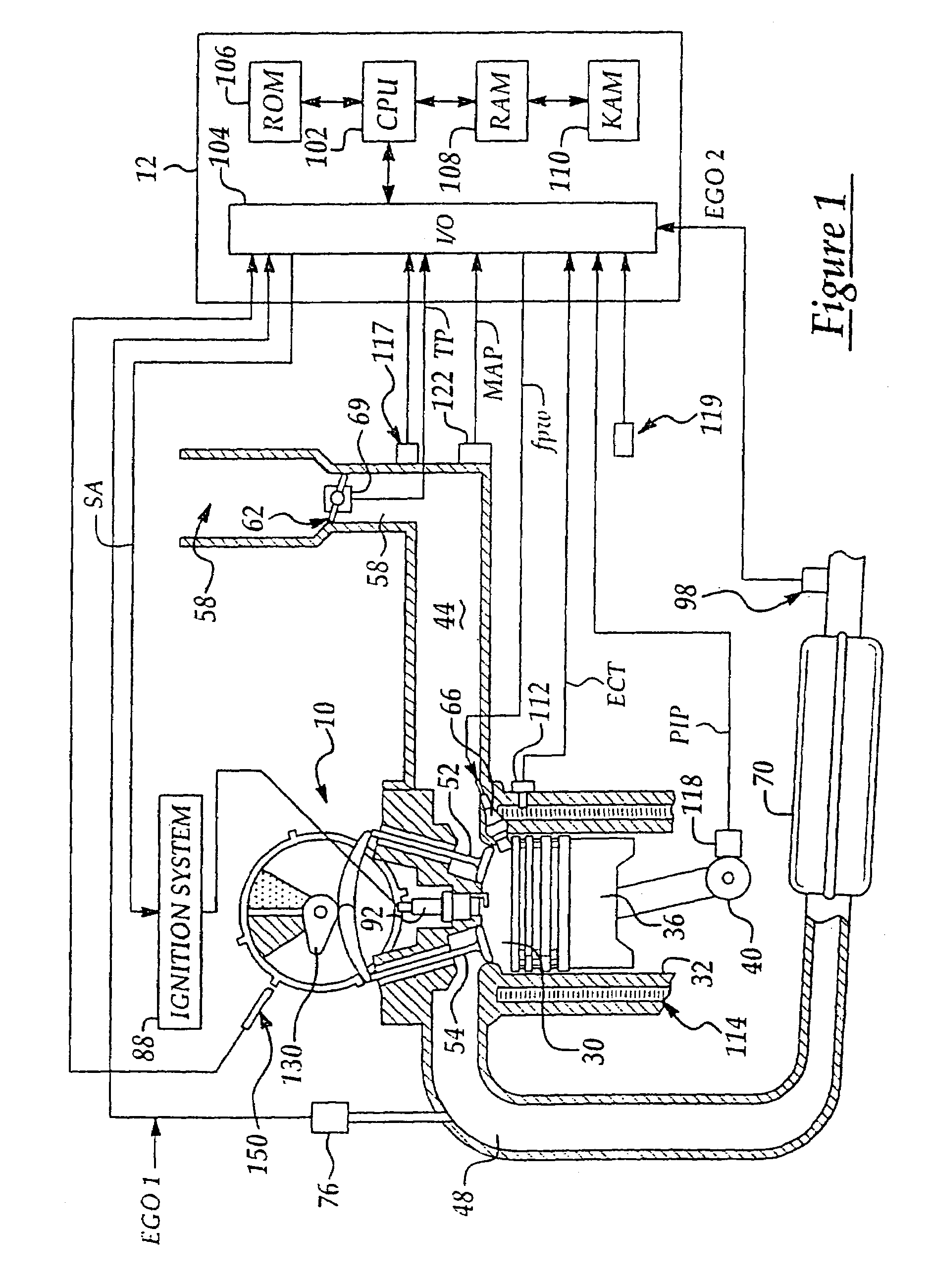
[0026]Referring to FIG. 1, internal combustion engine 10, comprising a plurality of cylinders, one cylinder of which is shown in FIG. 1, is controlled by electronic engine controller 12. Engine 10 includes combustion chamber 30 and cylinder walls 32 with camshaft 130 and piston 36 positioned therein and connected to crankshaft 40. Combustion chamber 30 is known communicating with intake manifold 44 and exhaust manifold 48 via respective intake valve 52 an exhaust valve 54. Combustion chamber 30 is also shown having fuel injector 66 coupled thereto for delivering liquid fuel in proportion to the pulse width of signal FPW from controller 12. Fuel is delivered to fuel injector 66 by fuel system (not shown) including a fuel tank, fuel pump, and fuel rail (not shown). Alternatively, the engine may be configured such that the fuel is injected directly into the intake manifold, directed at the cylinder port, which is known to those skilled in the art as port fuel injection. Intake manifold...


PUM


Abstract

A system and method to predict engine air amount for an internal combustion engine is described. Included is a method to predict a change in engine air amount based on engine position. This method especially suited to engine starts, where engine air amount is difficult to predict due to low engine speed and limited sensor information. The system and method provides the prediction of engine air amount without extensive models or calibration. Fuel is supplied based on the predicted engine air amount.

Description

CROSS-REFERENCE TO RELATED APPLICATIONS[0001]This application is a continuation of and claims priority to application Ser. No. 10 / 374,189, filed on Feb. 26, 2003 now U.S. Pat. No. 6,796,292, entitled “Engine Air Amount Prediction Based on Engine Position”, assigned to the same assignee as the present application, and incorporated herein by reference in its entirety.FIELD OF THE INVENTION[0002]The present invention relates to a method for controlling an internal combustion engine and more particularly to a method for adjusting injected fuel based on a prediction of air entering a cylinder for future induction events.BACKGROUND OF THE INVENTION[0003]Engine starting control has a significant impact on engine emissions. Conventional methods use several different approaches to start an engine. Some approaches use fixed fuel injection values based on empirical testing, while others read sensors and attempt to calculate fueling based on the current state of the sensor information[0004]One ...

Claims


Application Information

Patent Timeline
Patent Type & Authority Patents(United States)
IPC IPC(8): F02D41/06F02D45/00F02D41/18F02D41/32
CPCF02D41/062F02D41/32F02D41/18F02D2200/0402F02D41/04F02D41/30F02D41/065
Inventor LEWIS, DONALD JAMESRUSSELL, JOHN D.
Owner FORD GLOBAL TECH LLC
Learn More