Eureka AIR delivers breakthrough ideas for toughest innovation challenges, trusted by R&D personnel around the world.

Variable-power optical system, projection optical system, and image projection apparatus using the systems

a technology of optical systems and optical systems, applied in optics, optical elements, instruments, etc., can solve the problems of insufficient back focus length for reflection liquid crystal projectors, difficult to impart a higher zoom ratio thereto, and difficult to widen the angle, so as to reduce the overall lens system. the effect of back focus

Inactive Publication Date: 2006-01-24
CANON KK
View PDF12 Cites 17 Cited by
  • Summary
  • Abstract
  • Description
  • Claims
  • Application Information

AI Technical Summary

Benefits of technology

[0023]It is an object of the present invention to provide a variable-power optical system or a projection optical system suitable for a projection lens, for example, of a liquid crystal projector, which has a long back focus, while achieving downsizing of an overall lens system.

Problems solved by technology

Moreover, the negative lead type zoom lens has drawbacks that it is difficult to impart a higher zoom ratio thereto, it is difficult to widen the angle while restricting various aberrations, and so on.
However, in this six-unit zoom lens, a back focus length is insufficient for use in the reflection liquid crystal projector.
However, this four-unit zoom lens has a relatively large F-number for full aperture (hereinafter, the F-number represents it for full aperture), and does not obtain sufficient brightness.
However, when the same resolution is to be obtained by use of the small liquid crystal display elements, an aperture ratio of the liquid crystal display elements is lowered, and a size ratio of a region to be illuminated to a light emitting source (=size of the region to be illuminated / size of the light source) becomes gradually small.
Accordingly, illumination efficiency is lowered in general, causing a problem that the brightness falls even if the downsizing of the liquid crystal projector can be realized.

Method used


Image

  • Variable-power optical system, projection optical system, and image projection apparatus using the systems
  • Variable-power optical system, projection optical system, and image projection apparatus using the systems
  • Variable-power optical system, projection optical system, and image projection apparatus using the systems

Examples


first embodiment

(First Embodiment)

[0053]An embodiment of a variable-power optical system (zoom lens system) of the present invention will be described below with reference to the accompanying drawings.

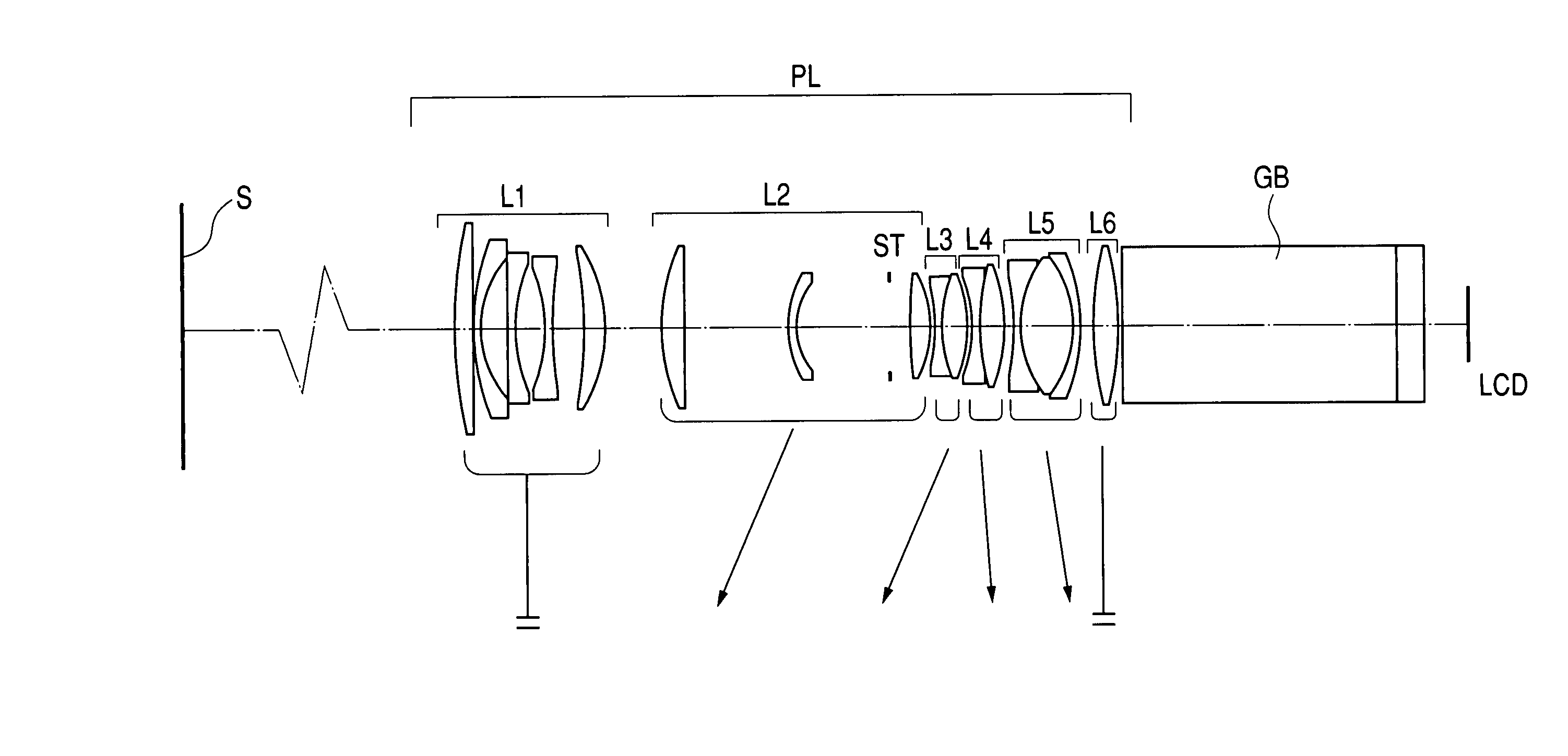
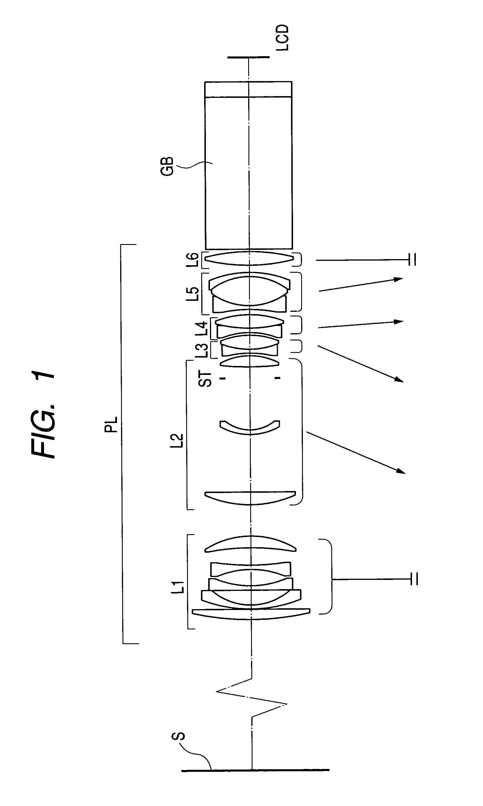
[0054]FIG. 1 is a schematic view of main portions of an image projection apparatus (liquid crystal video projector) using a zoom lens according to Embodiment 1 of the present invention. FIGS. 2A and 2B are aberration graphs at a wide angle end (short focal-length end) and a telescope end (long focal-length end) at an object distance (distance from a first lens unit to a screen) of 1.8 m when numeric values of Numerical Embodiment 1 described later, which corresponds to Embodiment 1 of the present invention, are expressed in millimeters.

[0055]FIG. 3 is a schematic view of main portions of an image projection apparatus (liquid crystal video projector) using a zoom lens according to Embodiment 2 of the present invention. FIGS. 4A and 4B are aberration graphs at a wide angle end (short focal-length end) a...

second embodiment

(Second Embodiment)

[0108]A projection optical system (projection lens) of a second embodiment of the present invention will be described below.

[0109]FIGS. 7 to 16 are schematic views of main portions of image projection apparatuses (liquid crystal video projectors) using projection lenses of Embodiments 4 to 13. FIGS. 17A to 26B are aberration graphs at wide angle ends (short focal-length ends) and telescope ends (long focal-length ends) when numeric values of Numerical Embodiments 4 to 13 to be described later, which correspond to Embodiments 4 to 13, are expressed in millimeters. In the aberration graphs, object distances (distances from first lens unit to screen) of Embodiments 4 to 7 are assumed to be 2.85 m, and object distances of Embodiments 8 to 13 are assumed to be 2.1 m.

[0110]In each of FIGS. 7 to 16, the left side is a screen side (enlargement conjugate side, front side), and the right side is an original picture side (reduction conjugate side, rear side). Moreover, refer...


PUM


Abstract

Disclosed is a variable-power optical system, including, sequentially from a front side to a rear side, a negative-refractive-power first lens unit that does not move for zooming, a positive-refractive-power second lens unit, a negative-refractive-power third lens unit, a fourth lens unit, a negative-refractive-power fifth lens unit, and a positive-refractive-power sixth lens unit that does not move for zooming, in which the following conditional expression is satisfied:1.7<bf / (|f1|·fw)1 / 2<2.3where f1 represents a focal length of the first lens unit, bf represents a back focus in air, and fw represents a focal length of an overall system at a wide angle end, whereby, while downsizing of an overall lens system is achieved, various aberrations accompanying zooming are well corrected, good optical performance is attained over an entire screen, and a wide angle of view and a long back focus are also attained.

Description

BACKGROUND OF THE INVENTION[0001]1. Field of the Invention[0002]The present invention relates to a variable-power optical system or a projection optical system, and the present invention is suitably applied to, for example, a projection optical system of an image projection apparatus which enlarges an original image and projects the enlarged original image on a screen (projection surface).[0003]2. Related Background Art[0004]Heretofore, a variety of liquid crystal projectors (image projection apparatuses), each of which uses an image display element such as a liquid crystal display element and projects an image (original image) displayed on the image display element on a screen surface (projection surface), have been proposed.[0005]In particular, as an apparatus capable of projecting an image of a personal computer and the like on a large screen, such a liquid crystal projector has been widely utilized in a conference, a presentation, and the like. Moreover, recently, a downsized li...

Claims


Application Information

Patent Timeline
Patent Type & Authority Patents(United States)
IPC IPC(8): G02B15/14G02B15/177
CPCG02B15/177G02B15/145527G02B15/144511G02B15/1465
Inventor YAMASAKI, SHINJINAKAYAMA, HIROKI
Owner CANON KK
Why Eureka
Eureka Blog
Learn More