
Zoom lens and image pickup apparatus including the same

a pickup apparatus and zoom lens technology, applied in the field of zoom lens and image pickup apparatus, can solve the problems of increasing the size of the lens in achieving a wider angle of view, the diameter of the first lens unit or the number of lenses or aspherical surfaces, and the inability to exchange lenses, etc., to achieve a wide angle of view, and reduce the size of the lens

Active Publication Date: 2019-05-21
CANON KK
View PDF68 Cites 5 Cited by
  • Summary
  • Abstract
  • Description
  • Claims
  • Application Information

AI Technical Summary

Benefits of technology

The solution enables a compact, high-performance zoom lens with a long back focus and high zoom ratio, effectively addressing the challenges of size and aberration variations, while maintaining a small F-number and achieving uniform resolution across the image plane.

Problems solved by technology

However, in order to greatly move the third lens unit and the fourth lens unit toward the object side during zooming, the third lens unit and the fourth lens unit are positioned near the image side at the wide angle end, and are not suitable as exchangeable lenses due to a short back focus.
However, the stop is away from the first lens unit, resulting in an increase in lens diameter of the first lens unit or an increase in number of lenses or number of aspherical surfaces.
However, the small refractive power of the first lens unit disadvantageously causes an increase in size in achieving a wider angle of view.
Further, only the second lens unit is mainly responsible for zooming, and hence a movement amount of the stop is disadvantageously increased in order to achieve both the downsizing of the first lens unit and the high zoom ratio.
When the setting of those is not appropriate, the entire system of the zoom lens is increased in size to achieve the higher zoom ratio, or variations of various aberrations accompanying zooming and focusing become larger, which results in extreme difficulty in obtaining high optical performance over the entire zoom range and the entire object distance.
However, as many as six to seven component lenses that form the first lens unit are arranged in order to push the principal point of the first lens unit to the image side, with the result that the first lens unit is disadvantageously heavy.

Method used


Image

  • Zoom lens and image pickup apparatus including the same
  • Zoom lens and image pickup apparatus including the same
  • Zoom lens and image pickup apparatus including the same

Examples


embodiment 1

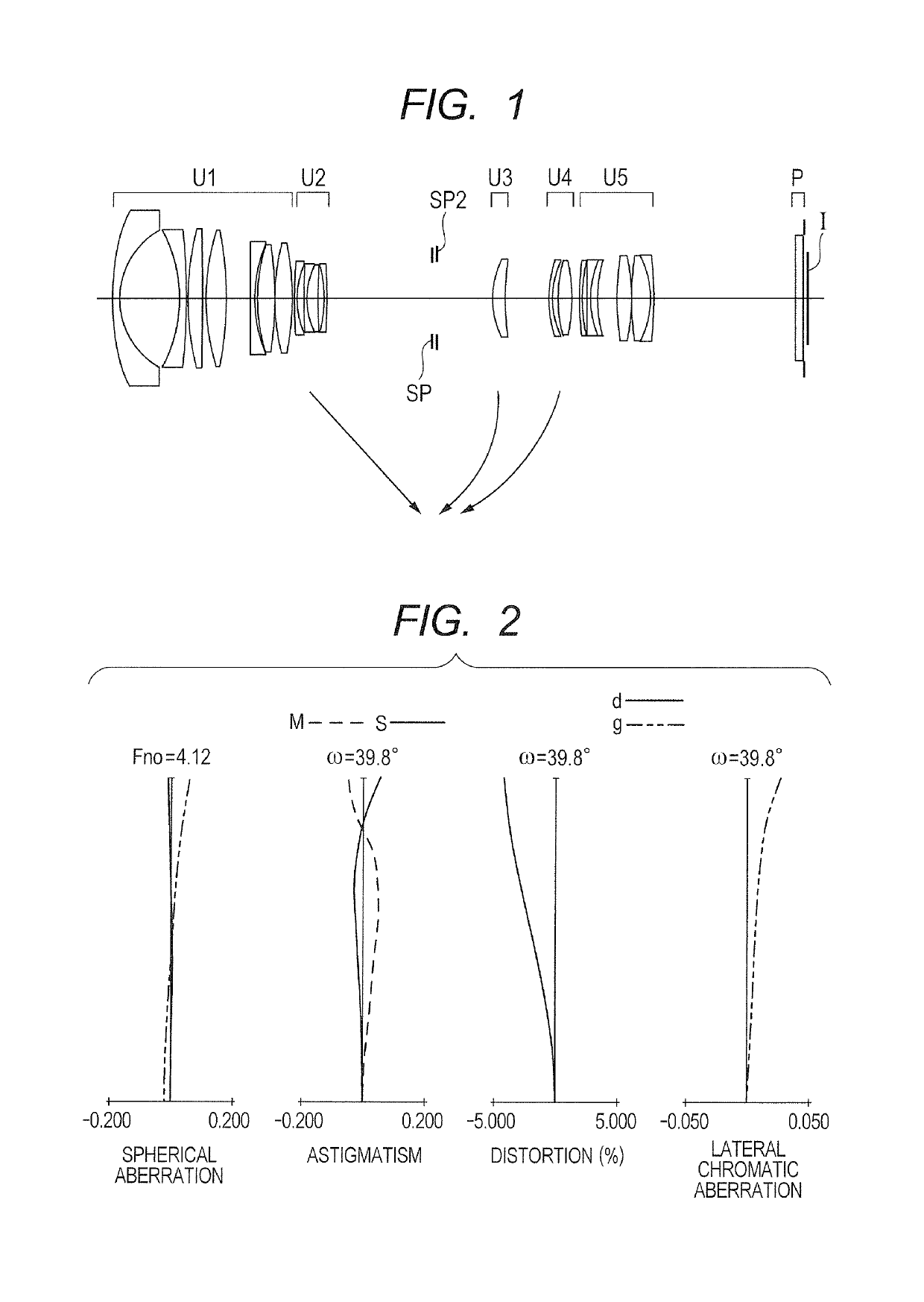
[0219]A zoom lens according to Embodiment 1 of the present invention includes, in order from the object side to the image side, a first lens unit U1 (front lens unit) having a positive refractive power, which is configured not to move for zooming, a second lens unit U2 (Nf lens unit) having a negative refractive power, which includes three or more lenses, an aperture stop SP, a third lens unit U3 (first rear lens unit) configured to move during zooming, a fourth lens unit U4 (second rear lens unit) configured to move during zooming, and a fifth lens unit U5 (third rear lens unit) configured not to move for zooming.

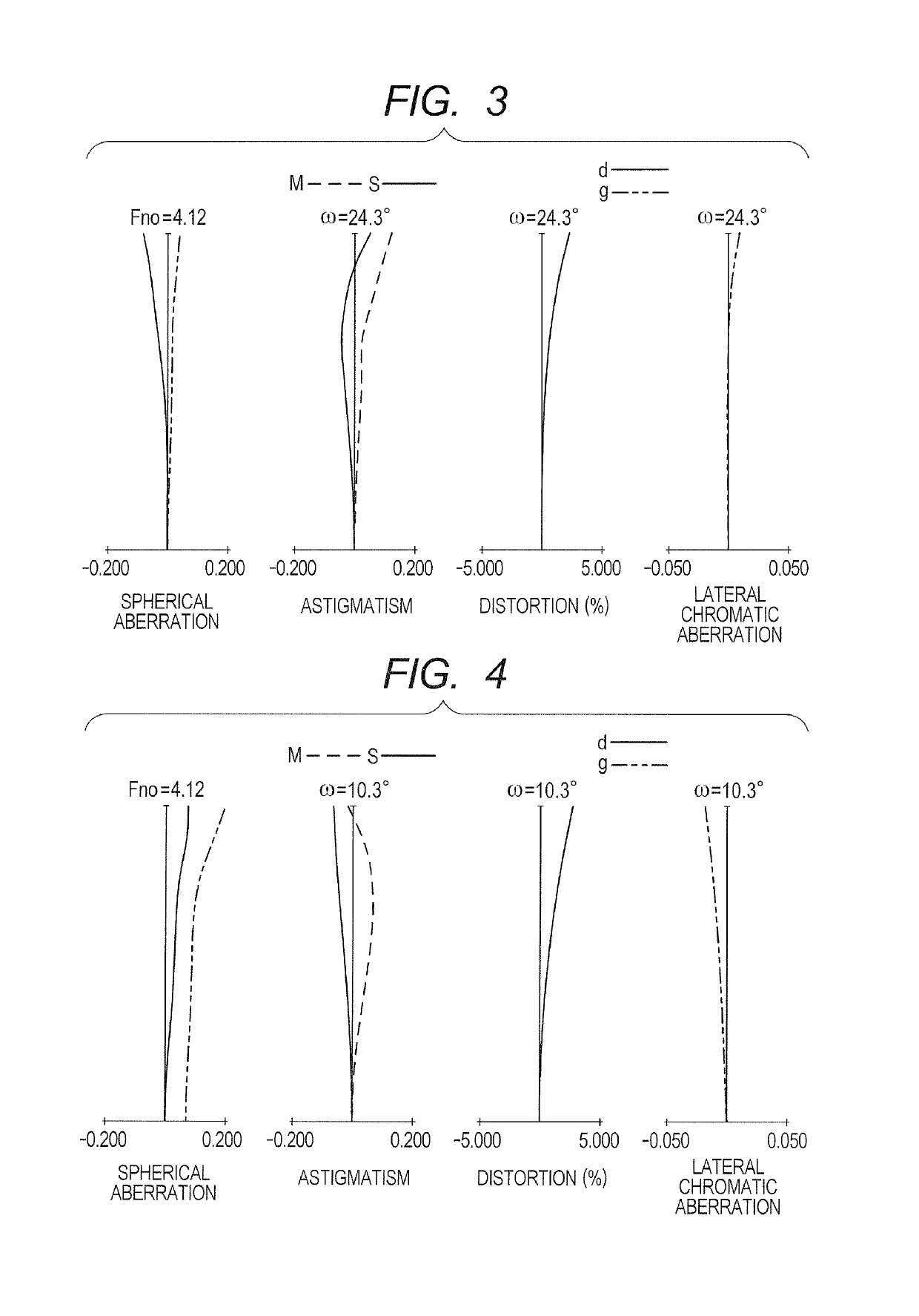
[0220]FIG. 1 is a lens cross-sectional view for illustrating the first lens unit U1, the second lens unit U2, the third lens unit U3, the fourth lens unit U4, the fifth lens unit U5, the aperture stop SP, an auxiliary stop SP2 configured to change the aperture diameter in order to determine an open F-number, a glass block P, e.g., a low-pass filter or a face plate of a CCD...

embodiment 2

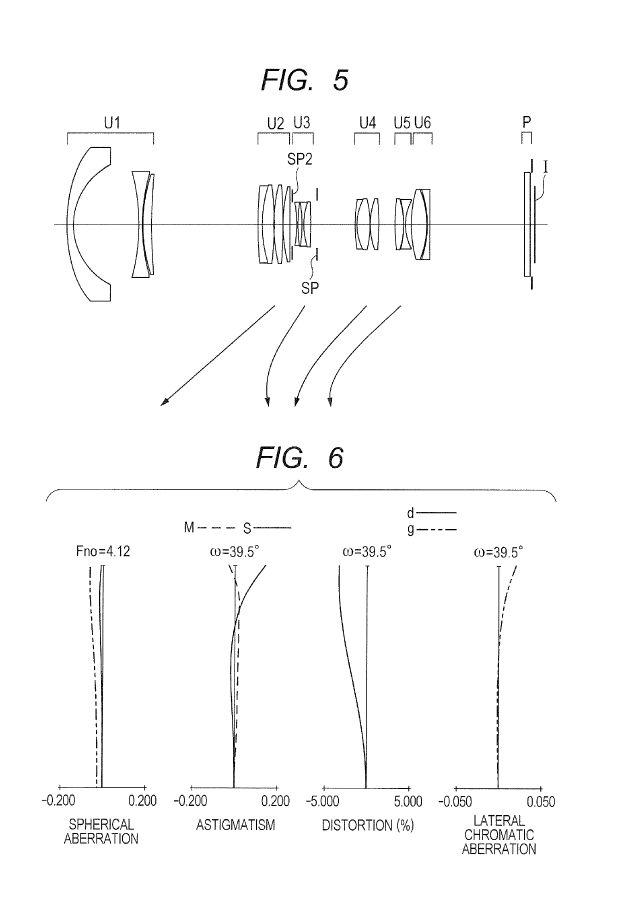
[0226]A zoom lens according to Embodiment 2 of the present invention includes, from the object side to the image side, a front lens unit, an Nf lens unit having a negative refractive power and including three or more lenses, an aperture stop, a first rear lens unit configured to move during zooming, a second rear lens unit configured to move during zooming, and a third rear lens unit configured not to move for zooming. Further, the front lens unit includes one or more lens units including a first lens unit configured not to move for zooming and arranged closest to the object side, and includes four or more lenses and one or more lens units having a positive refractive power.

[0227]The zoom lens according to Embodiment 2 includes the following components in order from the object side to the image side. The first lens unit U1 and the second lens unit U2 form the front lens unit. The first lens unit U1 corresponds to the first to sixth surfaces, and includes a meniscus negative lens hav...

embodiment 3

[0232]A zoom lens according to Embodiment 3 of the present invention includes, in order from the object side to the image side, a first lens unit U1 (front lens unit) having a positive refractive power, which is configured not to move for zooming, a second lens unit U2 (Nf lens unit) having a negative refractive power, which includes three or more lenses, an aperture stop SP, a third lens unit U3 (first rear lens unit) configured to move during zooming, a fourth lens unit U4 (second rear lens unit) configured to move during zooming, and a fifth lens unit U5 (third rear lens unit) configured not to move for zooming.

[0233]The zoom lens according to Embodiment 3 includes the following components in order from the object side to the image side. The first lens unit U1 corresponds to the front lens unit and to the first to thirteenth surfaces, and includes a meniscus negative lens having a surface concave on the image side, a biconcave lens, a meniscus positive lens having a surface conca...


PUM


Abstract

A zoom lens, includes, in order from object side: a front unit including a unit including a first unit arranged closest to the object side and not moving for zooming; an Nf unit including three or more lenses and having a negative refractive power; an stop; a first rear unit moving during zooming; a second rear unit moving during zooming; and a third rear unit not moving for zooming, in which: the front unit includes four or more lenses and includes one or more units having a positive refractive power; and a difference between positions of the first rear unit at a wide angle end and a telephoto end, a difference between positions of the second rear unit at the wide angle end and the telephoto end, a focal length of the second rear unit, and a focal length of the zoom at the wide angle end are appropriately set.

Description

BACKGROUND OF THE INVENTION[0001]Field of the Invention[0002]The present invention relates to a zoom lens and an image pickup apparatus including the zoom lens, which are suitable for, for example, a broadcasting television camera, a cinema camera, a video camera, a digital still camera, a monitoring camera, and a silver-halide film camera.[0003]Description of the Related Art[0004]In recent years, a large-sized solid state image pickup element has become widespread in order to obtain an image having high image quality and a shallow depth of field, but a zoom lens is required to become much smaller in order to avoid an increase in size of an entire camera system. In particular, a zoom lens having a wide angle of view at a wide angle end tends to have a larger front lens diameter, which greatly affects a weight of the zoom lens, and hence a wide-angle zoom lens having a small front lens diameter is desired.[0005]Hitherto, as a small-sized zoom lens capable of efficiently securing a ma...

Claims


Application Information

Patent Timeline
Patent Type & Authority Patents(United States)
IPC IPC(8): G02B15/14G02B15/173G02B15/177G02B15/17G02B15/16G02B15/20G02B15/24G02B9/60G02B9/62G02B5/00G02B27/64G02B7/04
CPCG02B15/173G02B15/161G02B15/17G02B15/177G02B15/20G02B27/646G02B7/04G02B9/60G02B9/62G02B15/14G02B15/24G02B5/005G02B15/142G02B15/144113G02B15/1465G02B15/145113
Inventor MIYAZAWA, NOBUYUKINAKAMURA, TOMOYUKIOGAWA, NAOTOSHISHIMOMURA, KAZUYA
Owner CANON KK
Learn More