
Antenna-integrated printed wiring board assembly for a phased array antenna system

a printed wiring board and antenna technology, applied in the field of phased array antenna systems, can solve the problems of requiring some complexity in dc power, logic and rf, and the bearing on the cost of the antenna assembly would be the material and process cost of manufacturing the antenna assembly, so as to reduce the independent number of component parts, reduce the manufacturing cost, and facilitate the assembly of the phased array antenna system

Inactive Publication Date: 2006-01-24
THE BOEING CO
View PDF10 Cites 44 Cited by
  • Summary
  • Abstract
  • Description
  • Claims
  • Application Information

AI Technical Summary

Benefits of technology

The present invention is a phased array antenna system that uses a printed wiring board assembly with a metal honeycomb waveguide plate eliminated in favor of a multi-layer printed wiring board. This reduces the number of component parts required and simplifies the assembly process, resulting in a lower manufacturing cost. The printed wiring boards are produced using an inexpensive process, and metal columns are formed during manufacture to improve electrical performance. The metal columns favorably influence the return loss bandwidth, probe-to-probe cross polarization isolation, insertion loss bandwidth, and higher order mode suppression, resulting in an improved operating bandwidth for a given antenna system. The inclusion of metal columns does not significantly complicate the manufacturing process or increase the overall cost of the antenna system.

Problems solved by technology

This approach requires some complexity for DC power, logic and RF distribution but it provides ample room for electronics.
If all of these independent parts could be substantially reduced in number or eliminated, then the primary issue bearing on the cost of the antenna assembly would be the material and process cost of manufacturing the antenna assembly.

Method used


Image

  • Antenna-integrated printed wiring board assembly for a phased array antenna system
  • Antenna-integrated printed wiring board assembly for a phased array antenna system
  • Antenna-integrated printed wiring board assembly for a phased array antenna system

Examples


Embodiment Construction

[0029]The following description of the preferred embodiment(s) is merely exemplary in nature and is in no way intended to limit the invention, its application, or uses.

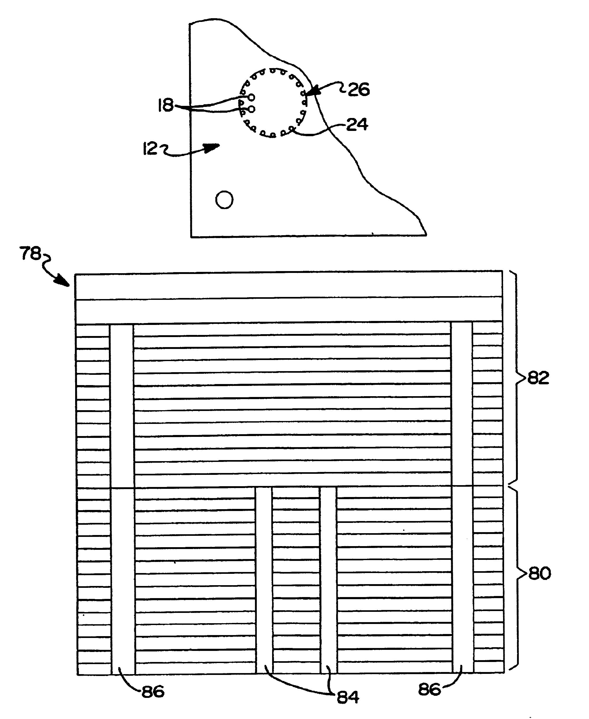
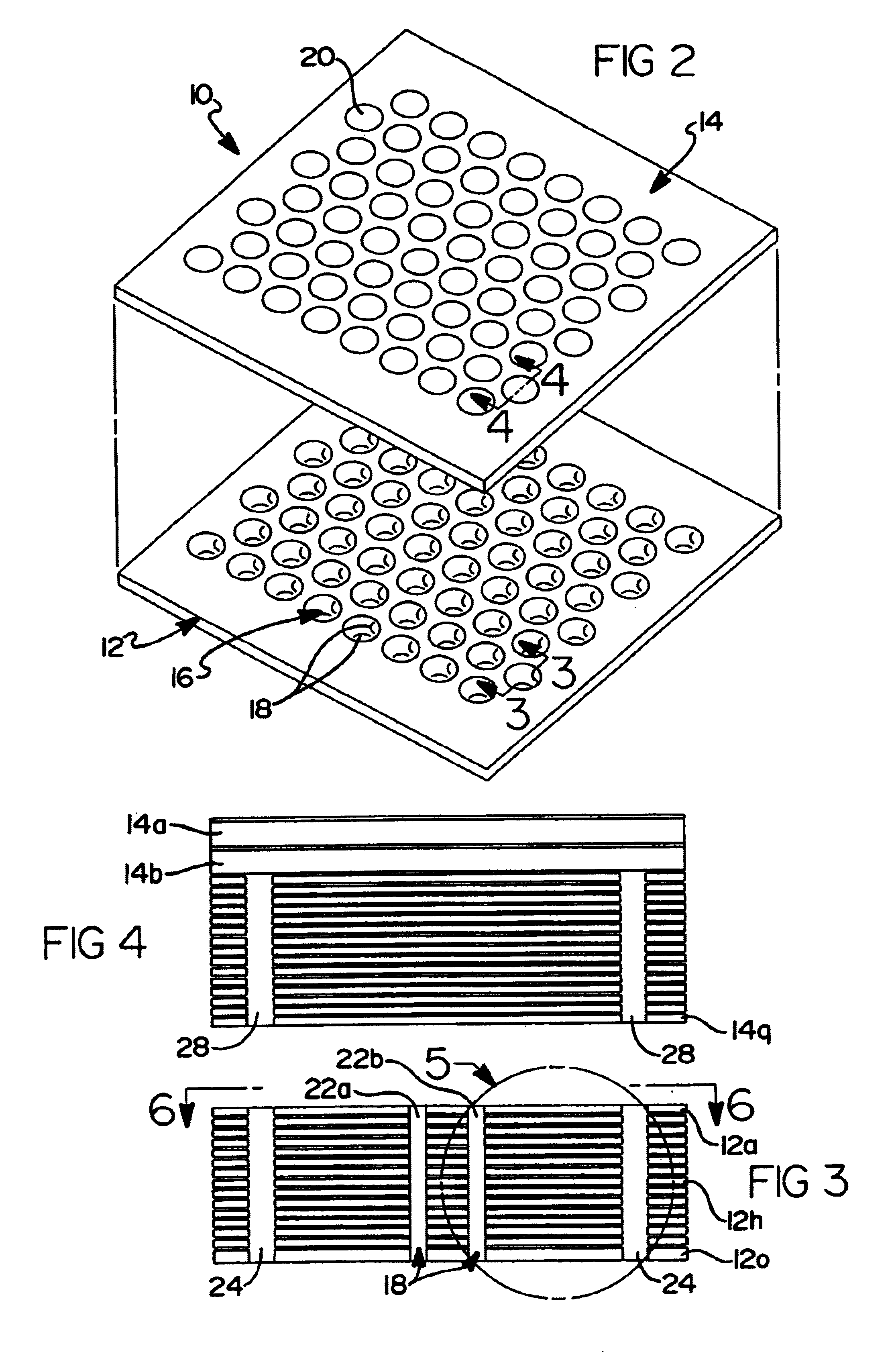
[0030]Referring to FIG. 2, there is illustrated a pre-assembled view of a 64 element phased array antenna system 10 in accordance with a preferred embodiment of the present invention. It will be appreciated immediately, however, that the present invention is not limited to a 64 element phased array antenna system, but that the principles and teachings set forth herein could be used to produce phased array antenna systems having a greater or lesser plurality of antenna elements. The phased array antenna system 10 incorporates a multi-layer probe-integrated printed wiring board 12 and a multi-layer waveguide printed wiring board 14 which are adapted to be disposed adjacent one another in abutting relationship when fully assembled. Conventional threaded or non-threaded fasteners (not shown) can be used to secure the two ...


PUM


Abstract

A phased array antenna system including a plurality of metal, column-like elements formed adjacent the RF probes for improving the electrical performance of the system. In one embodiment a hole is formed in a multi-layer, probe-integrated printed wiring board of the system and metal material is plated thereon to fill the hole. The metal, column-like elements are each disposed generally in between associated pairs of the RF probes. The metal, column-like elements essentially form metal pins that improve the return loss bandwidth, probe-to-probe isolation, insertion loss bandwidth, higher order mode suppression and cross-polarization generation.

Description

FIELD OF THE INVENTION[0001]The present invention relates to phased array antennas, and more particularly to a phased array antenna system incorporating at least one antenna module, and more preferably a plurality of antenna modules, and where each antenna module includes a metal column-like member that significantly improves cross polarization isolation between the RF radiating elements of each antenna module.BACKGROUND OF THE INVENTION[0002]The assignee of the present application, The Boeing Company, is a leading innovator in the design of high performance, low cost, compact phased array antenna modules. The Boeing antenna module shown in FIGS. 1a-1c have been used in many military and commercial phased array antennas from X-band to Q-band. These modules are described in U.S. Pat. No. 5,886,671 to Riemer et al and U.S. Pat. No. 5,276,455 to Fitzsimmons et al, both being hereby incorporated by reference.[0003]The in-line first generation module was used in a brick-style phased-arra...

Claims


Application Information

Patent Timeline
Patent Type & Authority Patents(United States)
IPC IPC(8): H01Q1/38H01Q21/00H01Q21/06
CPCH01Q21/064H01Q21/0075H01Q21/0093
Inventor NAVARRO, JULIO ANGELWHITE, GEOFFREY O.
Owner THE BOEING CO
Learn More