
Adjustable ablatable inlay

a technology of inlay and cornea, which is applied in the field of modifying a live cornea, can solve the problems of difficult access to the separated area to insert the inlay, the cornea is not easily damaged, so as to avoid or eliminate outbulging or instability, avoid or eliminate most of the risks of damage, and achieve precise separation

Inactive Publication Date: 2006-01-24
ACUFOCUS +1
View PDF39 Cites 53 Cited by
  • Summary
  • Abstract
  • Description
  • Claims
  • Application Information

AI Technical Summary

Benefits of technology

[0011]Accordingly, it is an object of the present invention to provide an improved method for modifying the cornea of an eye.
[0012]Another object of the present invention is to provide a method for modifying the cornea of an eye that results in a precise separation between layers in the cornea.
[0013]Still another object of the present invention is to provide a method for modifying the cornea of an eye that allows for corrective measures that avoid or eliminate outbulging or instability in the cornea.
[0014]Yet another object of the present invention is to provide a method for modifying the cornea of an eye that avoids or eliminates most of the risks of damage due to use of knives or other mechanical instruments.

Problems solved by technology

However, there can be problems when microkeratomies are used for cutting the cornea.
First, irregular keratectomies or perforations of the eye can result.
Second, the recovery of vision can be rather prolonged.
By separating the layers in the bottom two-thirds of the stromal, it is difficult to access the separated area to insert the inlay and virtually impossible to change or modify the inlay without another extensive surgical procedure.
However, because only certain amount of cornea can be ablated without the remaining cornea becoming unstable or experiencing outbulging (eklasisa), this technique is not especially effective in correcting very high myopia.
Use of these instruments may result in damage or imprecision in the cut or formation of the desired area in which the implant is placed.

Method used


Image

  • Adjustable ablatable inlay
  • Adjustable ablatable inlay
  • Adjustable ablatable inlay

Examples


Embodiment Construction

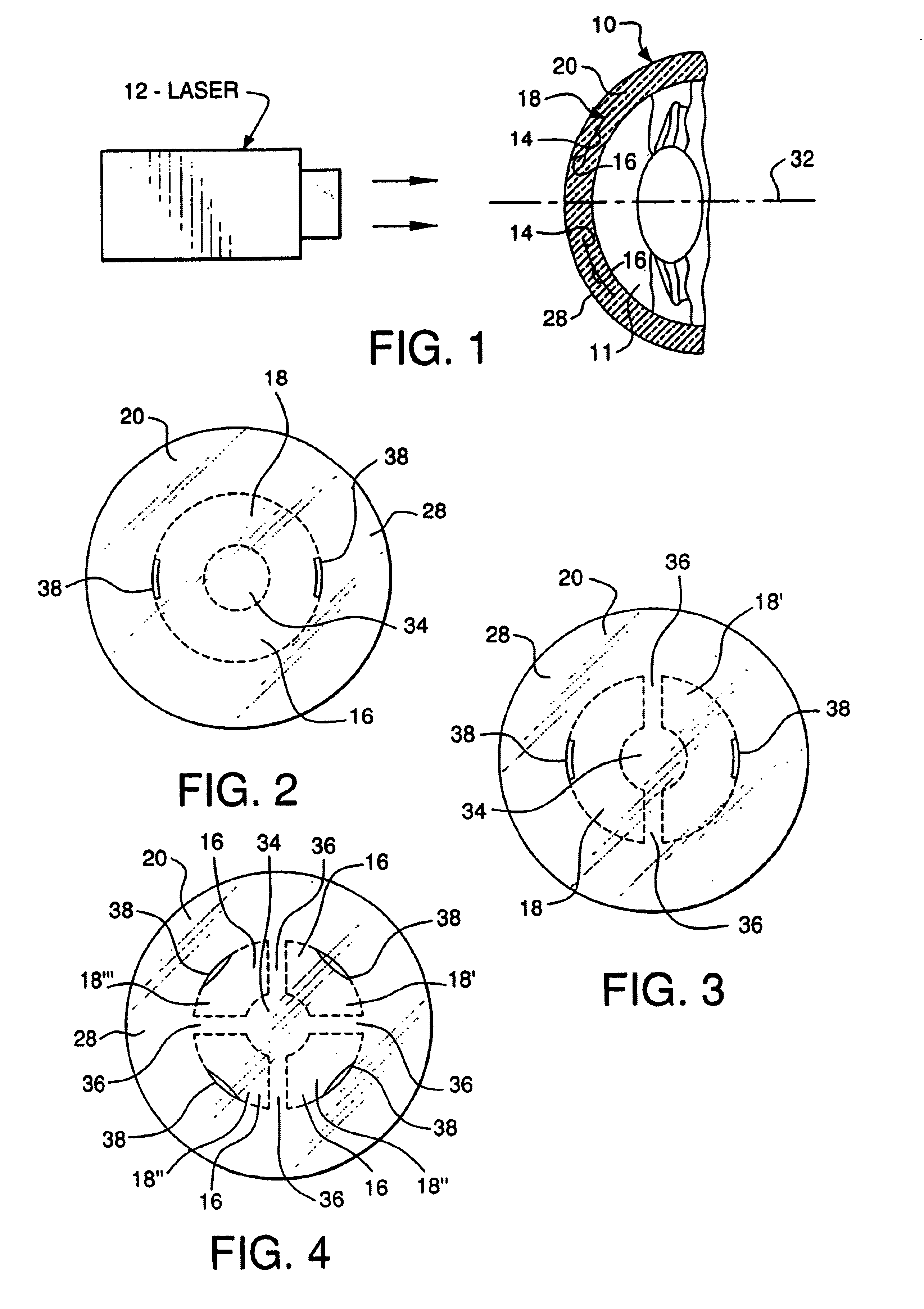
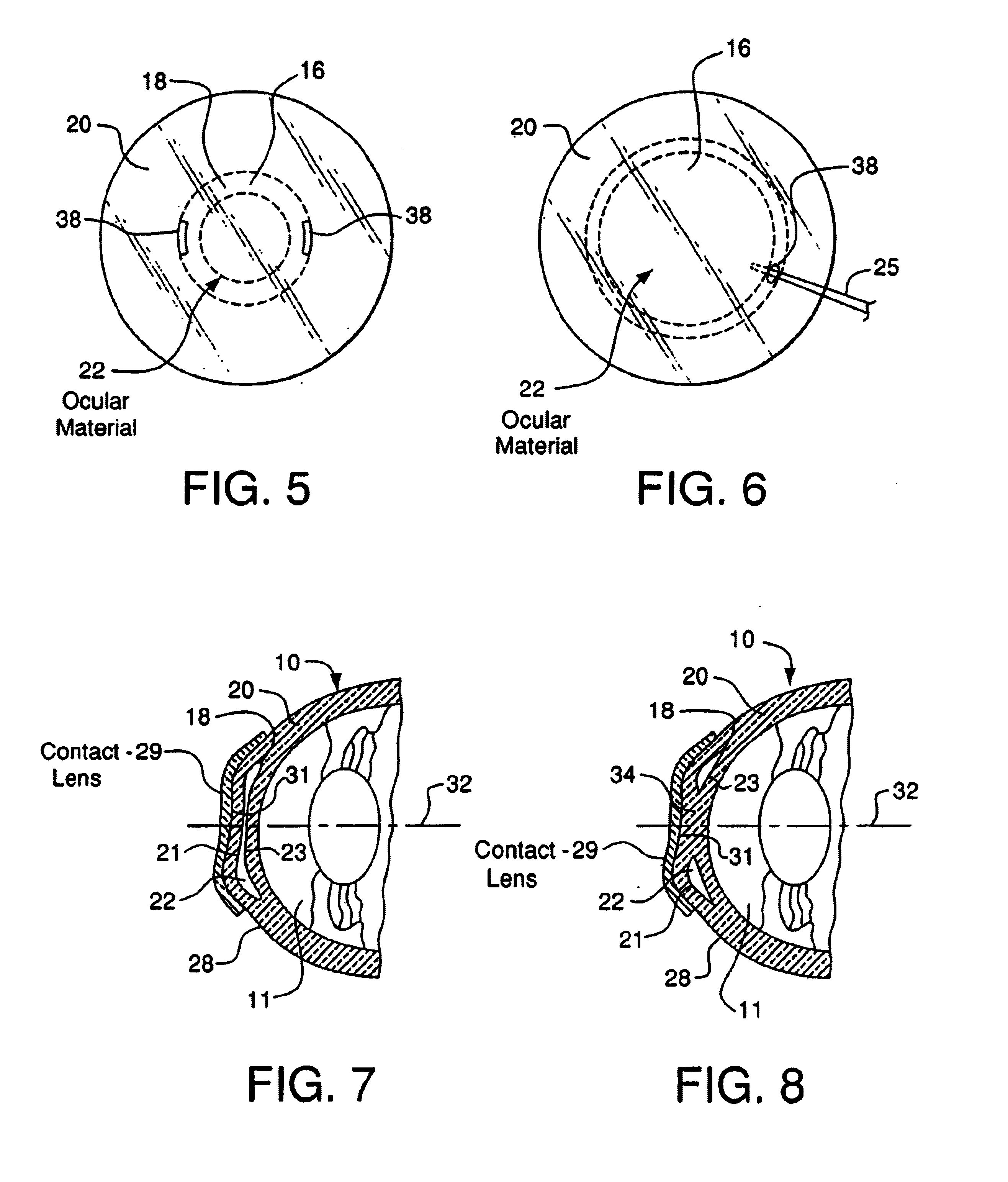
[0042]As initially shown in FIGS. 1, 2 and 19-24, the refractive properties of eye 10 can be altered by using laser 12 to separate an inner portion of the cornea into first internal corneal surface 14 and second internal corneal surface 16, creating internal corneal pocket 18 in the cornea 20 and then placing ocular material or an implant 22 in the pocket 18. Additionally, the cornea can be shaped by using a second laser 24 to ablate a portion 26 of the surface 28 of the cornea 16, or an external lens 29 to mold the ocular material.

[0043]To begin, the refractive error in the eye is measured using wavefront technology, as is known to one of ordinary skill in the art. For a more complete description of wavefront technology see U.S. Pat. No. 6,086,204 to Magnate, the entire contents of which is incorporated herein by reference. The refractive error measurements are transmitted to a computerized lathe (not shown) or other lens-shaping machine, where the shape of ocular material is deter...


PUM


Abstract

A method of modifying a cornea of an eye to reduce refractive error, the cornea having a surface and a main optical axis, including the steps of aiming and firing a laser at the cornea of the eye. The laser first separates an internal portion of the cornea forming a first internal surface and a second internal surface, the first internal surface facing in a posterior direction of the cornea and the second internal surface facing in an anterior direction of the cornea, with the first and second internal surfaces forming an internal pocket therebetween. An incision is then made from the surface of the cornea to the internal pocket, and an ocular implant is introduced through the incision and into the internal pocket of the cornea.

Description

RELATED APPLICATIONS[0001]This application is related to U.S. application Ser. No. 09 / 758,263, filed Jan. 12, 2001, the entire contents of which are herein incorporated by reference.FIELD OF THE INVENTION[0002]The present invention relates to a method for modifying a live cornea to correct refractive error. In particular, the live cornea is modified by using a laser to separate an internal area of the live cornea into first and second opposed internal surfaces, which define a pocket therebetween. An ocular material is then introduced into the pocket, which changes the shape of the cornea. Additionally, the ocular material can be irradiated, which will cause a portion of the ocular material to expand or contract, thereby further changing the shape of the cornea.BACKGROUND OF THE INVENTION[0003]A conventional method for correcting the refractive error in a cornea is keratophakia, i.e., implantation of a lens inside the cornea. Keratophakia uses an implant which is placed into the corn...

Claims


Application Information

Patent Timeline
Patent Type & Authority Patents(United States)
IPC IPC(8): A61B18/18A61B18/00A61F9/00A61F9/008A61F9/01A61F9/013
CPCA61F2/145A61F9/008A61F9/00806A61F9/00812A61F9/0017A61F2009/0088A61F9/00819A61F9/00836A61F9/013A61F2009/00872A61F2/147
Inventor PEYMAN, GHOLAM A.
Owner ACUFOCUS
Learn More