Hybrid vehicle

Inactive Publication Date: 2006-01-24
HONDA MOTOR CO LTD
View PDF20 Cites 28 Cited by
  • Summary
  • Abstract
  • Description
  • Claims
  • Application Information

AI Technical Summary

Benefits of technology

[0010]In consideration of the above circumstances, an object of the present invention is to provide a hybrid vehicle in which drivability is improved, and in which vehicle behavior is stable even when switching back and forth between an engine cruise mode and a motor cruise mode.
[0012]According to the hybrid vehicle configured as described above, the motor cruise mode can be effectively used in a driving state in which the engine cannot run with high efficiency. In addition, when the driving mode of the vehicle is switched from the engine cruise mode to the motor cruise mode, a drag feeling due to a fuel cut operation can be reduced, and when the driving mode of the vehicle is switched from the motor cruise mode to the engine cruise mode, a combustion initiation jolt due to start of the engine operation can be also reduced.
[0014]According to the hybrid vehicle configured as described above, the pumping loss of the engine can be reduced during the motor cruise mode. In addition, a vehicle jolt, which is caused by changes in the friction of the engine due to stop or start of the operations of the intake and exhaust valves when the driving mode of the vehicle is switched between the engine cruise mode and the motor cruise mode, can be reduced by controlling the clutch section in a manner described above.
[0017]According to the hybrid vehicle configured as described above, a vehicle jolt, which is caused by changes in the friction of the engine due to stop of the operations of the intake and exhaust valves when the driving mode of the vehicle is switched from the engine cruise mode to the motor cruise mode, can be eliminated.
[0019]According to the hybrid vehicle configured as described above, a frequent switching of the driving mode between the engine cruise mode and the motor cruise mode, i.e., a hunting phenomenon, can be prevented.
[0023]According to the hybrid vehicle configured as described above, a frequent switching of the driving mode between the engine cruise mode and the motor cruise mode, i.e., a hunting phenomenon, can be prevented.

Problems solved by technology

Conventionally, in such a hybrid vehicle, the motor-generator is not used solely for driving the vehicle (hereinafter this driving mode is referred to as a “motor cruise mode”) because, in a motor cruise mode, the engine is a portion of the load for the motor-generator, and the motor-generator must produce power to compensate for the pumping loss and friction of the engine; therefore, fuel efficiency may not be improved when compared with the case in which the engine is used solely for driving the vehicle (hereinafter this driving mode is referred to as an “engine cruise mode”).
In such a hybrid vehicle which may be driven by a motor, a problem is encountered in that an unexpected deceleration feeling or jolt (hereinafter referred to as a drag feeling) is experienced when the driving mode of the vehicle is switched between the motor cruise mode and the engine cruise mode, alternately.
More specifically, when the driving mode of the vehicle is switched from the engine cruise mode to the motor cruise mode, a drag feeling is experienced due to cut of fuel supply to the engine along with a jolt (vehicle vibration) due to changes in the engine friction by stopping the operations of the intake and exhaust valves.
On the other hand, when the driving mode of the vehicle is switched from the motor cruise mode to the engine cruise mode, another drag feeling is experienced due to changes in the engine friction by starting the operations of the intake and exhaust valves along with a combustion initiation jolt due to start (ignition) of the engine operation.

Method used


Image

  • Hybrid vehicle
  • Hybrid vehicle
  • Hybrid vehicle

Examples


Embodiment Construction

[0043]An embodiment of the hybrid vehicle according to the present invention will be explained below with reference to FIGS. 1 to 18.

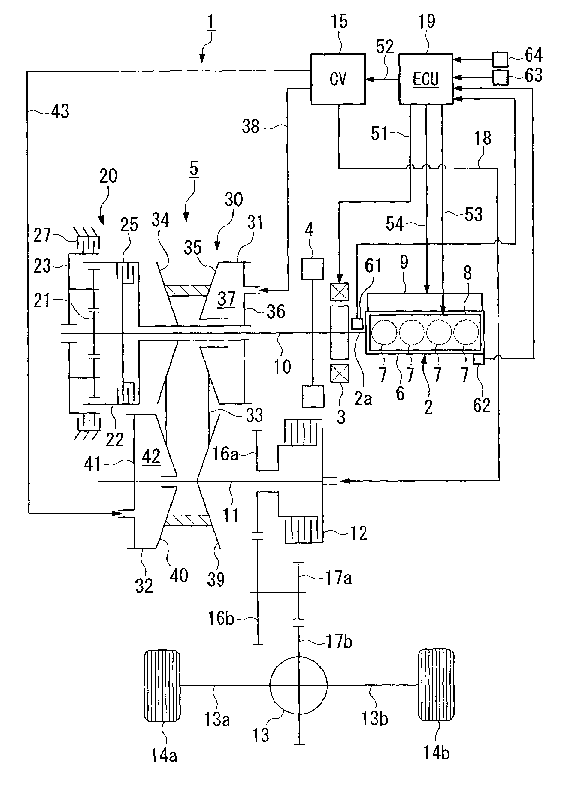
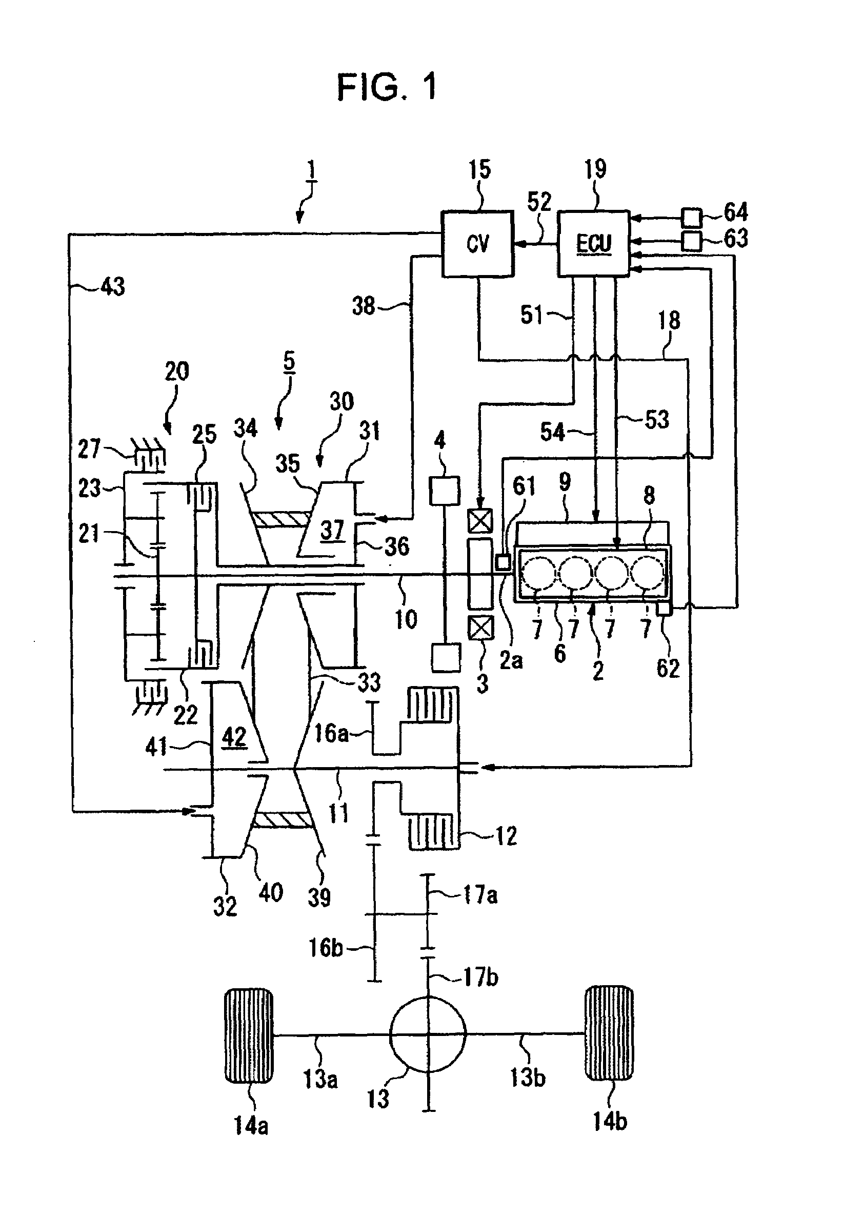
[0044]FIG. 1 is a diagram showing the general structure of the driving power transmission system in an embodiment of the hybrid vehicle according to the present invention. The driving power transmission system of the hybrid vehicle 1 comprises an engine 2, motor 3 (hereinafter referred to as a motor-generator) which is capable of generating electrical power, and which is disposed on an output shaft 2a of the engine 2, and a pulley and belt type continuously variable transmission (CVT) 5 connected to the engine output shaft 2a via a coupling mechanism 4.

[0045]The engine 2 is a four-cylinder reciprocating engine in which pistons are respectively provided in four cylinders 7 formed in an engine block 6. The engine 2 comprises an intake-exhaust control device 8 which controllably operates intake valves and exhaust valves for executing drawing and dischargi...


PUM


Abstract

A hybrid vehicle having an engine and a motor as power sources that generate electrical power, and an output shaft to which driving power from at least one of the engine and the motor is transmitted for driving the vehicle. The vehicle may be driven in an engine cruise mode wherein the vehicle is driven only by the engine, or in a motor cruise mode wherein the vehicle is driven only by the motor. A clutch section provided between the engine and motor and a pair of axle shafts selectively disconnects the driving powers of the engine and the motor. A control section controls the clutch section, wherein the driving mode of the vehicle is alternately switched between the engine cruise mode and the motor cruise mode. As such, an engagement degree of the clutch section is decreased at switching, and then gradually increased until it is totally recovered.

Description

BACKGROUND OF THE INVENTION[0001]1. Field of the Invention[0002]The present invention relates to a vehicle, generally known as a hybrid vehicle, which comprises, as power sources, an engine and a motor, the motor also being capable of generating electrical energy, the vehicle obtaining driving power from at least one of the engine and the motor.[0003]2. Description of the Related Art[0004]In recent years, in order to conserve fuel in the running of engines, or to reduce exhaust gas produced by combustion of fuel, hybrid vehicles have been developed, each of which comprises an engine and a motor, the motor also being capable of generating electrical energy (hereinafter referred to as a motor-generator) that are connected to a power transmission mechanism connected to driving wheels, and in which the motor-generator produces supplemental driving power depending on demand during normal travel of the vehicle, and the motor-generator is connected to the driving wheels so as to convert a ...

Claims


Application Information

Patent Timeline
IPC IPC(8): B60K1/00B60K6/485B60W20/00B60K6/543B60K17/04B60L15/20B60L50/16B60W10/02B60W10/04B60W10/06B60W10/08F02D17/02F02D29/02F02N11/04F16D48/02
CPCB60K6/387B60K6/485B60K6/543B60W10/02B60W10/06B60W10/08B60W20/00Y10T477/26B60W2520/10B60W2540/10B60W2710/023Y02T10/6226Y02T10/6286Y02T10/7258Y02T10/62Y02T10/72B60W2050/0052B60W20/10
Inventor TATARA, YUSUKEFUKUDA, TOSHIHIKOIKEMATSU, TOMOFUMIHASEBE, TETSUYA
Owner HONDA MOTOR CO LTD
Why Eureka
Try Eureka