Dynamic quantity sensor

a sensor and dynamic technology, applied in the field of dynamic quantity sensors, can solve the problems of sensor output tending to vary, and achieve the effect of detecting sensor failures easily and accurately

Inactive Publication Date: 2006-01-24
DENSO CORP
View PDF9 Cites 6 Cited by
  • Summary
  • Abstract
  • Description
  • Claims
  • Application Information

AI Technical Summary

Benefits of technology

[0003]In view of the above-described problems, the present invention has an object to provide a dynamic quantity sensor capable of easily and accurately detecting sensor failure in an event that the sensor output is fixed to a reference level.

Problems solved by technology

However, the sensor output tends to vary due to aging effect occurring in the circuit elements constituting the sensor or due to ambient temperature or the like.

Method used


Image

  • Dynamic quantity sensor
  • Dynamic quantity sensor
  • Dynamic quantity sensor

Examples


Embodiment Construction

Fundamental Arrangement

[0020]FIG. 6 is a block diagram showing the basic arrangement of a capacitance type acceleration sensor that is one of dynamic quantity sensors.

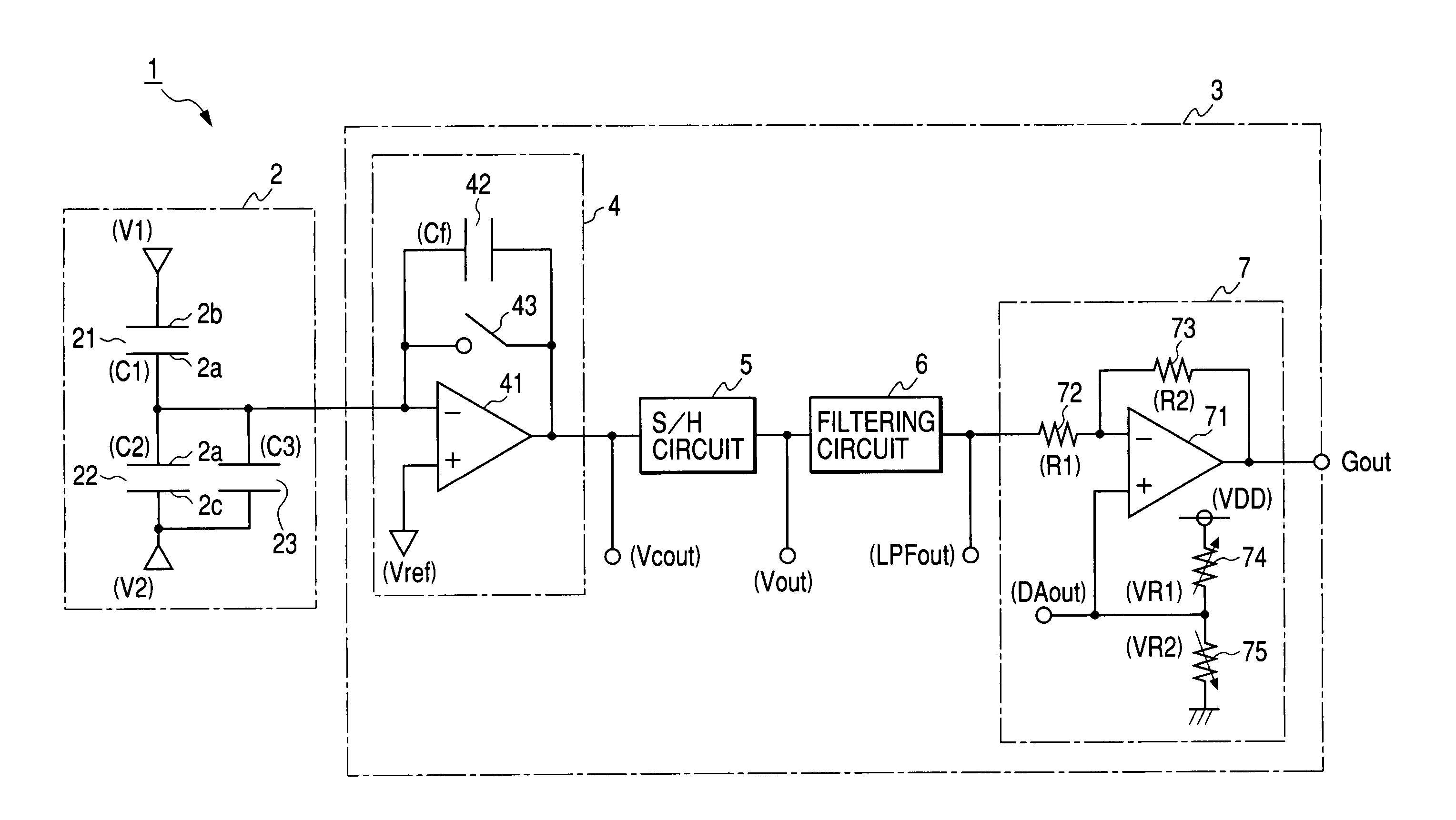
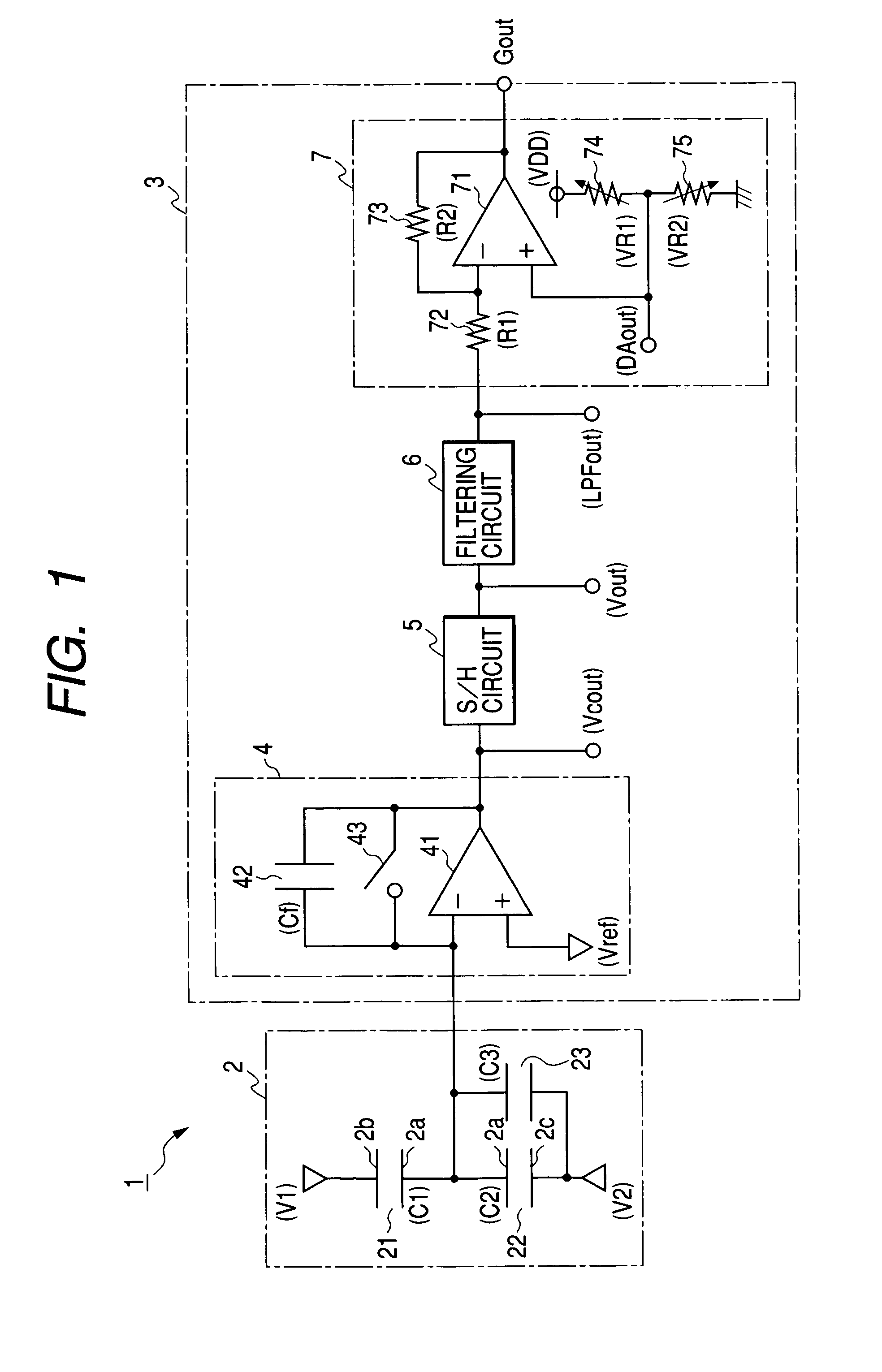
[0021]As shown in FIG. 6, a capacitance type acceleration sensor 101 includes a sensor element 102 and a detection circuit 103. The sensor element 102, formed on a substrate, has a beam structure that is capable of causing a displacement relative to the substrate in response to the acceleration or any other applied dynamic quantity. The capacitance type acceleration sensor 101 has a movable electrode2a integrally formed with the beam structure and two stationary electrodes 2b and 2c disposed at both sides of the movable electrode 2a and fixed to the substrate. The movable electrode 2a and two stationary electrodes 2b and 2c are arranged so as to cooperatively define two differential capacitors 21 and 22.

[0022]More specifically, the beam structure causes a displacement in response to the acceleration applied to a body o...


PUM

PropertyMeasurementUnit
voltageaaaaaaaaaa
capacitance C2+C3aaaaaaaaaa
voltage DAoutaaaaaaaaaa

Abstract

A sensor element includes a pair of differential capacitors having capacitances C1 and C2 causing a complementary capacitance change in response to an applied acceleration. An additional capacitor is connected to either capacitor to generate a capacitance difference between the capacitance C1 and the composite capacitance C2+C3. This enables to adjust an input LPFout of a correcting circuit correcting the offset level of the sensor output Gout in such a manner that a correction amount in the correcting circuit becomes large and accordingly deviates sufficiently from a reference level Vref. In case of failure in which the input of the correcting circuit is fixed to the reference level Vref, the sensor output Gout surely deviates from the reference level Vref by an amount equivalent to the correction in the correcting circuit.

Description

BACKGROUND OF THE INVENTION[0001]The present invention relates to a dynamic quantity sensor used for detecting various dynamic quantities, such as acceleration, angular velocity, voltage or the like.[0002]For example, an acceleration sensor, as one of dynamic quantity sensors, is used for collision detection in an airbag system or any other automotive device. However, the sensor output tends to vary due to aging effect occurring in the circuit elements constituting the sensor or due to ambient temperature or the like.SUMMARY OF THE INVENTION[0003]In view of the above-described problems, the present invention has an object to provide a dynamic quantity sensor capable of easily and accurately detecting sensor failure in an event that the sensor output is fixed to a reference level.[0004]To accomplish the above and other related objects, the present invention provides a dynamic quantity sensor that includes a signal generating section generating a detection signal having a signal level...

Claims


Application Information

Patent Timeline
Patent Type & Authority Patents(United States)
IPC IPC(8): G01P15/125G01L1/14
CPCG01P15/125
Inventor FURUICHI, AKIHISA
Owner DENSO CORP
Why Eureka
Try Eureka