
Wireless and powerless sensor and interrogator

a technology of power-free sensor and interrogator, which is applied in the direction of instruments, child seats, pedestrian/occupant safety arrangements, etc., can solve the problems of not being able to focus on small features of the display, being very distracting, and being able to add many more functions, etc., and achieve the effect of less for

Inactive Publication Date: 2006-01-17
AMERICAN VEHICULAR SCI
View PDF1 Cites 712 Cited by
  • Summary
  • Abstract
  • Description
  • Claims
  • Application Information

AI Technical Summary

Benefits of technology

[0266]3. To provide an early warning of a potential component failure and to thereby minimize the cost of repairing or replacing the component.
[0401]The invention also encompasses a vehicle including the above-described determining system, adjustment system and projector with the interacting system being an optional modification. In this case, the projector and / or seat would be adjusted to ensure that the mouth of the occupant is positioned optimally relative to the sensitive direction of the microphone to thereby provide optimum reception of the occupant's voice by the microphone.

Problems solved by technology

A vehicle driver is not going to be able to focus intently on small features of the display.
On the other hand, the potential exists for adding many more functions, some of which may become very distracting.
It is envisioned, therefore, that implementation of the system will be in stages and to a large degree will be concomitant with the evolution of other safety systems such as autonomous vehicles.
Most of the capacitance technologies described require the conductivity of the operator's finger and therefore will not functions if the driver is wearing gloves.
For thicker gloves, the projected capacitive systems become necessary with an additional loss of resolution.
Thin metal oxide films on thin plastic films can also be used, however, the durability of this system can be a serious problem.
This requirement may also be incompatible with an airbag deployment doors unless the pad is placed wholly on one flap of the deployment door or multiple pads are used each on a single flap.
Aside from this possible design, and designs using a matrix or tube structure described below, it is unlikely that surface acoustic wave or other ultrasonic systems will be applicable.
These voice systems are not 100% accurate and heretofore there has been no effective means to provide feedback to the operator of the vehicle indicating what the voice system understood.
Although several prior art patents have disclosed the capability of adjusting the heads up display, none of them have done so based on a determination of the location of the eyes of the occupant.
One of the problems with heads up displays as described in the prior art patents is that sometimes the intensity of light coming in from the environment makes it difficult to see the information on the heads up display.
More complicated messages become possible when vehicles are autonomously driven.
Thus, the state of the vehicle could be normal when the vehicle is operating properly on a highway or abnormal when, for example, the vehicle is experiencing excessive angular inclination (e.g., two wheels are off the ground and the vehicle is about to rollover), the vehicle is experiencing a crash, the vehicle is skidding, and other similar situations.

Method used


Image

  • Wireless and powerless sensor and interrogator
  • Wireless and powerless sensor and interrogator
  • Wireless and powerless sensor and interrogator

Examples


first embodiment

[0852]Referring now to FIGS. 20A-20B, a valve cap 149 including a tire pressure monitoring system in accordance with the invention is shown generally at 10 in FIG. 20A. A tire 140 has a protruding, substantially cylindrical valve stem 141 which is shown in a partial cutaway view in FIG. 20A. The valve stem 141 comprises a sleeve 142 and a tire valve assembly 144. The sleeve 142 of the valve stem 141 is threaded on both its inner surface and its outer surface. The tire valve assembly 144 is arranged in the sleeve 142 and includes threads on an outer surface which are mated with the threads on the inner surface of the sleeve 142. The valve assembly 144 comprises a valve seat 143 and a valve pin 145 arranged in an aperture in the valve seat 143. The valve assembly 144 is shown in the open condition in FIG. 20A whereby air flows through a passage between the valve seat 143 and the valve pin 145.

[0853]The valve cap 149 includes a substantially cylindrical body 148 and is attached to the ...

second embodiment

[0855]a valve cap 10′ in accordance with the invention is shown in FIG. 20B and comprises a SAW strain sensing device 154 that is mounted onto a flexible membrane 152 attached to the body 148 of the valve cap 149 and in a position in which it is exposed to the air in the chamber 151. When the pressure changes in chamber 151, the deflection of the membrane 152 changes thereby changing the stress in the SAW device 154.

[0856]Strain sensor 154 is thus a differential pressure-measuring device. It functions based on the principle that changes in the flexure of the membrane 152 can be correlated to changes in pressure in the chamber 151 and thus, if an initial pressure and flexure are known, the change in pressure can be determined from the change in flexure.

[0857]FIGS. 20A and 20B therefore illustrate two different methods of using a SAW sensor in a valve cap for monitoring the pressure inside a tire. The precise manner in which the SAW sensors 150,154 operate is discussed fully below but...


PUM


Abstract

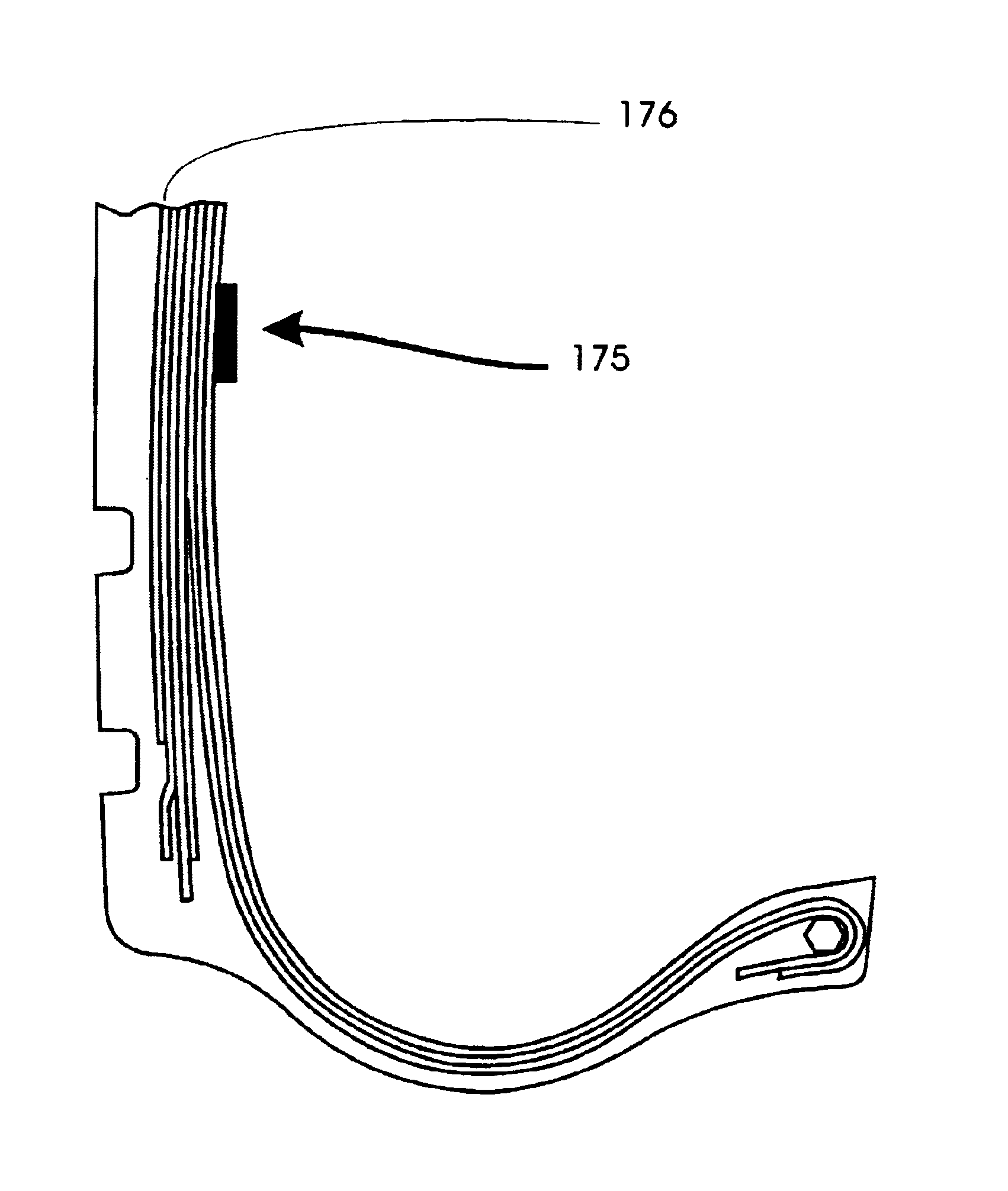
Arrangement and method for monitoring a tire mounted to the vehicle in which a thermal radiation detecting device detects the temperature of the tire at different circumferential locations along the circumference of the tire. The detected temperatures of the tire are analyzed to determine, for example, whether a difference in thermal radiation is present between the circumferential locations of the tire, and if so, an action is effected in response to the analysis. The thermal radiation detecting devices are preferably supplied with power wirelessly, e.g., through an inductive system, a capacitive system or a radio frequency energy transfer system.

Description

CROSS REFERENCE TO RELATED APPLICATIONS[0001]This application is:[0002]1) a continuation of U.S. patent application Ser. No. 10 / 188,673 filed Jul. 3, 2002, now U.S. Pat. No. 6,738,697 which is a continuation-in-part of U.S. patent application Ser. No. 09 / 753,186 filed Jan. 2, 2001, now U.S. Pat. No. 6,484,080, which is a continuation-in-part of U.S. patent application Ser. No. 09 / 137,918 filed Aug. 20, 1998, now U.S. Pat. No. 6,175,787, which is a continuation-in-part of U.S. patent application Ser. No. 08 / 476,077 filed Jun. 7, 1995, now U.S. Pat. No. 5,809,437;[0003]2) a continuation-in-part of U.S. patent application Ser. No. 10 / 174,709 filed Jun. 19, 2002 now U.S. Pat. No. 6,735,506;[0004]3) a continuation-in-part of U.S. patent application Ser. No. 10 / 330,938 filed Dec. 27, 2002 now U.S. Pat. No. 6,823,244;[0005]4) a continuation-in-part of U.S. patent application Ser. No. 10 / 613,453 filed Jul. 3, 2003;[0006]5) a continuation-in-part of U.S. patent application Ser. No. 09 / 925,06...

Claims


Application Information

Patent Timeline
Patent Type & Authority Patents(United States)
IPC IPC(8): G06F7/00B60C11/24B60C19/00B60C23/04B60C23/06B60N2/02B60N2/28B60R21/00B60R21/16B60R21/20B60R21/213B60R21/231B60R21/233B60R21/235B60R21/30G02B27/00G02B27/01G06V10/143G06V30/194G07C5/00G07C5/08
CPCG07C5/0808G07C5/008B60C11/24B60C19/00B60C23/0449B60N2/0276B60N2/2863B60R21/20B60R21/213B60R21/232B60R21/233B60R21/235B60R21/30B60R2021/0004B60R2021/23107B60R2021/23153B60R2021/23161B60R2021/23169B60R2021/23519B60R2021/23523B60R2021/23557B60R2021/2358B60R2021/2359G02B27/01G02B2027/014G02B2027/0187G06K7/10178B60C11/246G06V20/593G06V20/59G06V10/143G06V30/194G06F18/2411B60N2/0272B60N2/02246
Inventor BREED, DAVID S.DUVALL, WILBUR E.JOHNSON, WENDELL C.KOLOMEYKO, ANATOLIY V.SHOSTAK, OLEKSANDR T.
Owner AMERICAN VEHICULAR SCI
Learn More