Apparatus for plating solution analysis

a plating solution and apparatus technology, applied in the direction of liquid/fluent solid measurement, material electrochemical variables, instruments, etc., can solve the problems of residual additives contained within the tubes, the inability to accurately inject a microliter or less of additives into the plating solution, and the inability to efficiently fill the void-free interconnect feature by conventional deposition techniques

Inactive Publication Date: 2006-01-17
APPLIED MATERIALS INC
View PDF29 Cites 10 Cited by
  • Summary
  • Abstract
  • Description
  • Claims
  • Application Information

AI Technical Summary

Benefits of technology

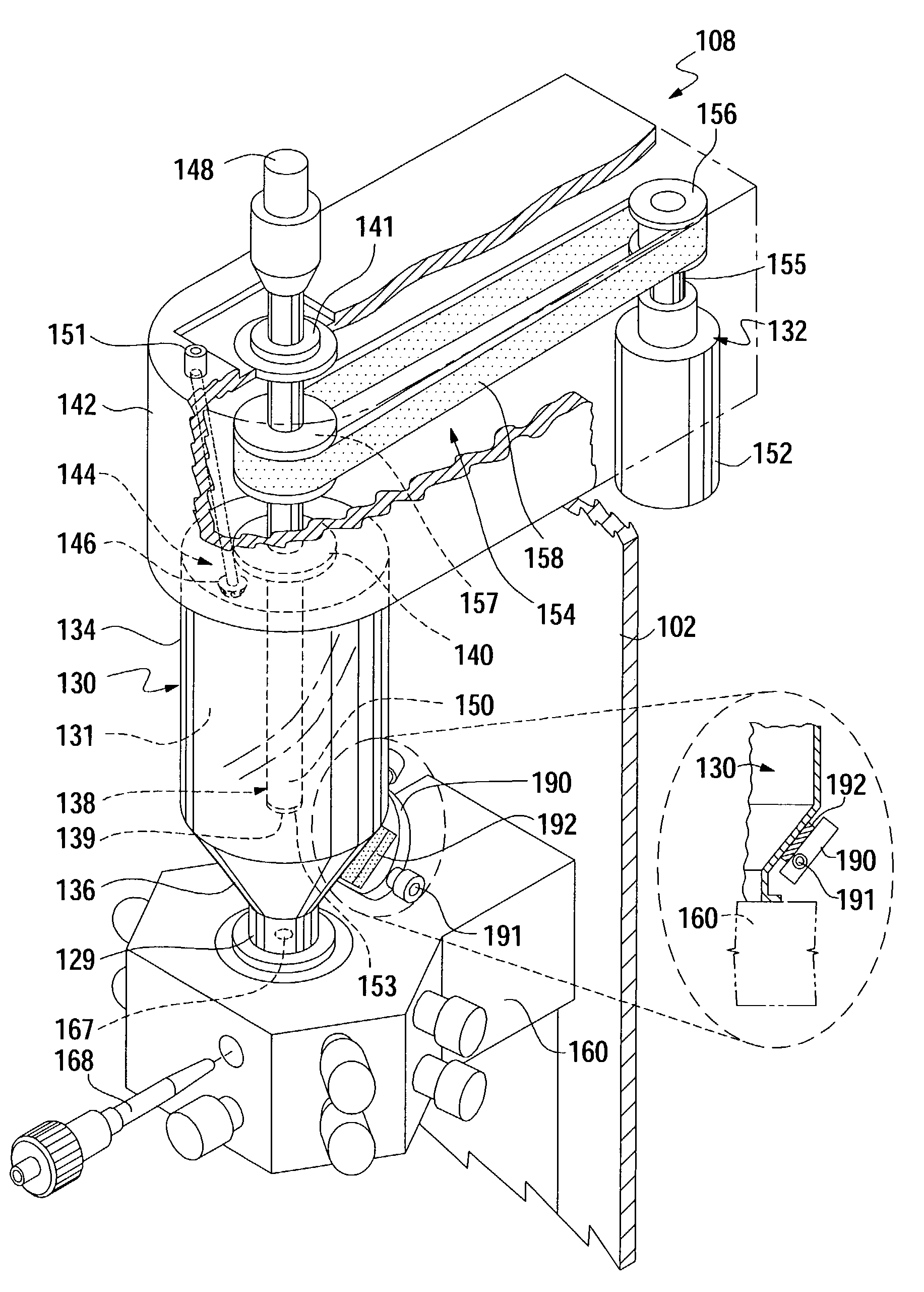
[0009]Embodiments of the invention generally provide an apparatus for analyzing one or more solutions used in a plating process. In one embodiment, the invention provides an apparatus for analyzing plating solutions, wherein the apparatus includes a vessel defining a cavity having a larger volumetric portion adjacent a smaller volumetric portion. Generally, the larger and smaller volumetric portions are adapted to hold solutions. The apparatus further includes a rotating electrode disposed within the cavity, and a fluid injection apparatus coupled to a bottom portion of the vessel adjacent the smaller volumetric region, wherein the fluid injection apparatus is adapted to inject one or more fluids into at least some of the one or more solutions.
[0010]In another embodiment, the invention provides an apparatus for analyzing plating solutions used in a substrate plating process. The apparatus includes a vessel defining a cavity adapted to hold the plating solutions, a rotatable working electrode extending at least partially within the cavity, and a motor disposed on top of the vessel and adapted to rotate the working electrode. The apparatus further includes a base coupled to a lower portion of the cavity adjacent a bottom portion of the vessel, wherein the base includes a plurality of fluid ports for coupling fluids from external fluid sources to the cavity. The base further includes a connection member having an upper surface in communication with at leas

Problems solved by technology

However, as interconnect sizes decrease and aspect ratios increase, efficient void-free interconnect feature fill by conventional deposition techniques becomes increasingly difficult.
Unfortunately, as/test volumes may vary from a few milliliters to several hundred milliliters, the cell size must be changed accordingly to accommodate the differing test volumes.
Further, as tubes or syringes are used to inject the additives into the plating solutions, it is difficult to accurately inject a microliter or less of the additives into the plating sol

Method used


Image

  • Apparatus for plating solution analysis
  • Apparatus for plating solution analysis
  • Apparatus for plating solution analysis

Examples


Embodiment Construction

[0020]FIG. 1 illustrates a perspective view of a plating solution analysis device 105 useful in practicing the invention. In one embodiment, the plating solution analysis device 105 includes a frame 101 that may be divided into functional sections to allow for ease of service and to separate electronic devices from fluids used during testing. The basic sections include a test section 103, a rear electronics section 106, and a grab sample compartment 107. In one aspect, the plating solution analysis device 105 includes a plating cell 108 disposed on the frame 101 within the test section 103. The plating cell 108 is described below with respect to FIG. 2A. In one configuration, the plating solution analysis device 105 may include a reference electrolyte container 112 used to hold electrolytes, such as potassium chloride or other reference electrolytes. A reference electrolyte pump 118 may be adapted to pump reference electrolytes from the reference electrolyte container 112 to the pla...


PUM


Abstract

A method and apparatus for analyzing plating solutions. The apparatus generally includes a plating cell, a reference electrolyte input, one or more external additive pumps, and a process controller. In one embodiment, the plating cell includes a cavity therein having a larger volumetric portion adjacent a smaller volumetric portion adapted to hold one or more solutions therein. The plating cell also includes a base disposed adjacent the bottom of the plating cell and adapted to receive and mix one or more test solutions as part of the plating solution analysis. In one configuration, the base includes electrical ports adapted to connect stimulation signals to a working electrode, counter electrode, and reference electrode disposed within the cell. The base also includes a thermal sensor in thermal contact with test solutions contained within the vessel.

Description

BACKGROUND OF THE INVENTION[0001]1. Field of the Invention[0002]Embodiments of the invention generally relate to an apparatus and method for conducting chemical analysis of substrate plating solutions.[0003]2. Description of the Related Art[0004]Metallization of sub-quarter micron sized features is a foundational technology for present and future generations of integrated circuit manufacturing processes. More particularly, in devices such as ultra large scale integration-type of devices, i.e., devices having integrated circuits with more than a million logic gates, the multilevel interconnects that lie at the heart of these devices are generally formed by filling high aspect ratio interconnect features with a conductive material, such as copper or aluminum, for example. Conventionally, deposition techniques such as chemical vapor deposition (CVD) and physical vapor deposition (PVD) have been used to fill interconnect features. However, as interconnect sizes decrease and aspect ratio...

Claims


Application Information

Patent Timeline
IPC IPC(8): G01N27/403G01N27/48
CPCG01N27/48
Inventor BALISKY, TODD ALANCAMERON, DONALD A.SUN, ZHI-WEN
Owner APPLIED MATERIALS INC
Why Eureka
Try Eureka