
Heating/air conditioning installation for motor vehicle including main module forming fluid-carrying heat exchanger

Inactive Publication Date: 2006-01-17
VALEO SYST THERMIQUES
View PDF29 Cites 25 Cited by
  • Summary
  • Abstract
  • Description
  • Claims
  • Application Information

AI Technical Summary

Benefits of technology

[0008]The invention particularly makes it possible to bring together, in regards to relative position, the gas cooler, especially a condenser, and the evaporator, which is beneficial in terms of the cost of pipework. Moreover, the invention makes it possible to reduce the number of connections through the bulkhead or to group together all these connections which are sources of possible leaks of refrigerant fluid.
[0027]The thermal loop may exhibit a third routing circuit in order, in a thermal heating mode, to form a heating loop and including the compressor and the main exchanger and the auxiliary exchanger as appropriate, the refrigerant-fluid outlet of the main exchanger being coupled to the inlet of the compressor, either directly or via a pressure-reducing valve. This pressure-reducing valve can be arranged downstream of the main exchanger, which enhances the thermal exchanges, since the refrigerant fluid in the gaseous state is hotter.
[0028]The heating loop may exhibit a pressure-reducing valve arranged before or after the main exchanger, which makes it possible to work with a lower-density fluid, which enhances the efficiency, and at lower speed, and thus with lower noise. In the mode of heating via the refrigerant fluid, the circulation of heat-carrying fluid (especially of water) can be allowed or prevented on the basis of the temperature discrepancies between the two fluids and of the overall throughput of the system.

Problems solved by technology

Moreover, all the solutions described above exhibit the drawback of making use of a heating element (heating radiator) which operates only in cold weather or in order to de-humidify, and a condenser which operates only in hot weather or in order to dehumidify.

Method used


Image

  • Heating/air conditioning installation for motor vehicle including main module forming fluid-carrying heat exchanger
  • Heating/air conditioning installation for motor vehicle including main module forming fluid-carrying heat exchanger
  • Heating/air conditioning installation for motor vehicle including main module forming fluid-carrying heat exchanger

Examples


Embodiment Construction

[0050]The invention applies more particularly to heating / air-conditioning apparatus which exhibits a mixing flap on the air.

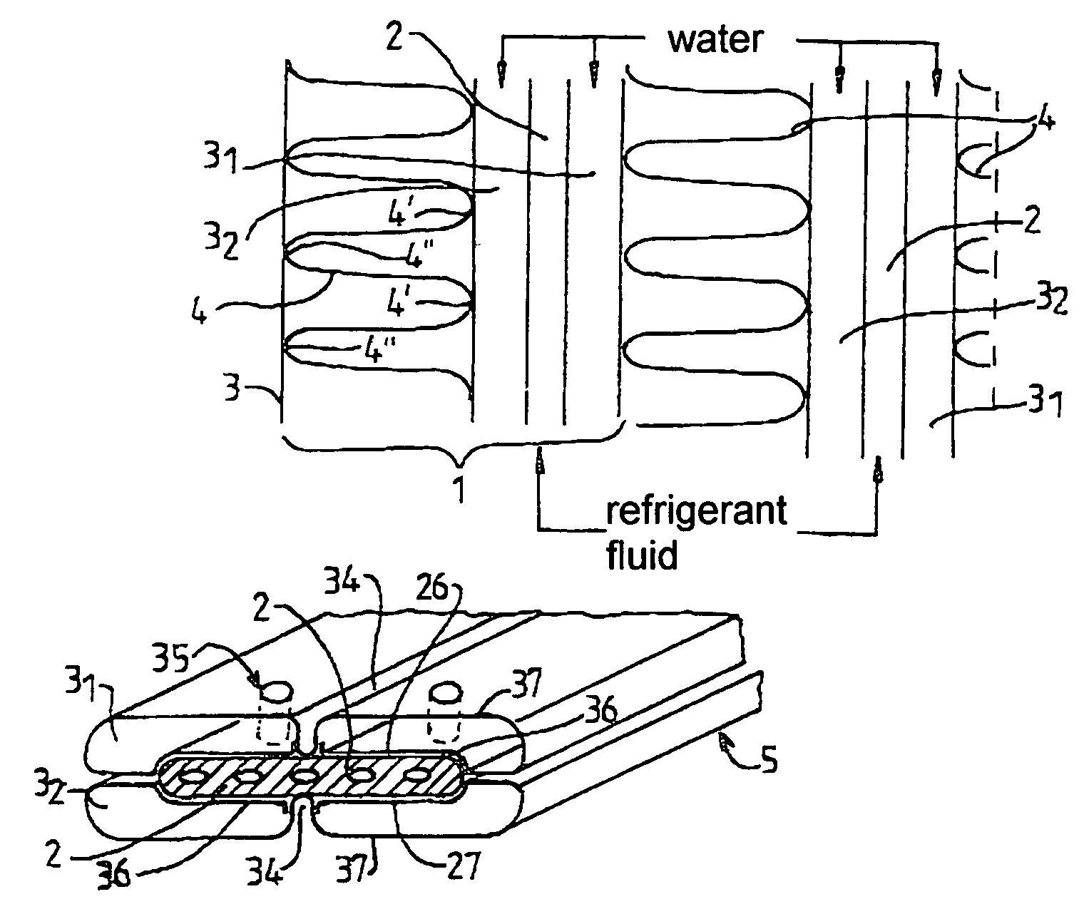
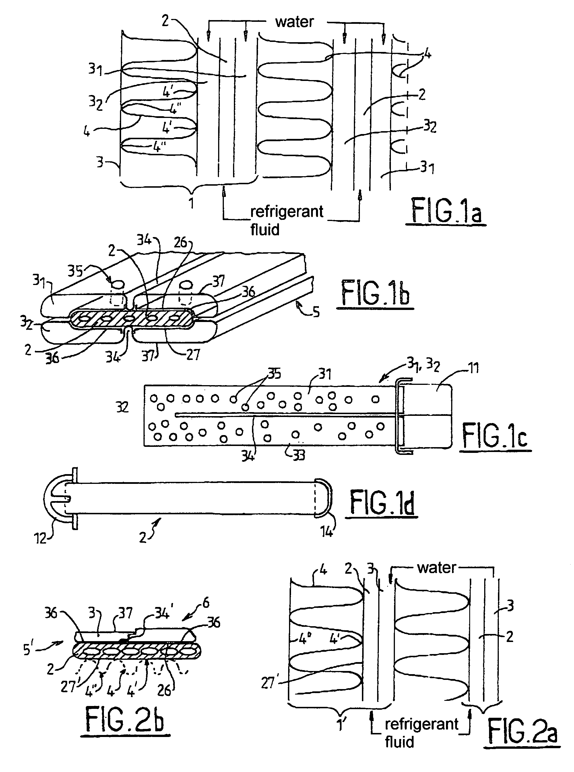
[0051]The basic idea of the present invention is thus to use a heat-carrying fluid / air / refrigerant-fluid exchanger which fulfils respectively the roles of gas cooler or of radiator on the basis of the operating modes chosen. In the case of a “conventional” thermal loop, the gaseous refrigerant fluid is condensed in the gas cooler which constitutes a condenser. In the case of a thermal loop operating in what is known as “supercritical” mode, the gaseous refrigerant fluid, for example CO2, is simply cooled in the gas cooler.

[0052]The rest of the invention relates, in a nonlimiting way, to the case of a conventional thermal loop, which employs a condenser and in which the heat-carrying fluid is water.

[0053]The first embodiment described in FIGS. 1a to 1d makes it possible to give maximum preference to the exchange between water tubes and refrigerant-fluid tubes. A...


PUM

PropertyMeasurementUnit
Timeaaaaaaaaaa
Flow rateaaaaaaaaaa

Abstract

A heating / air-conditioning installation for a motor vehicle has a thermal loop which includes a refrigerating compressor, a gas cooler, a pressure-reducing valve, an evaporator, and a heating element. The gas cooler and the heating element are grouped together into a single exchanger including a main module forming a main fluid-carrying heat exchanger.

Description

FIELD OF THE INVENTION[0001]The subject of the present invention is a heating / air-conditioning installation for a motor vehicle, comprising, on the one hand, a thermal loop which includes a refrigerating compressor, a condenser, a pressure-reducing valve and an evaporator and, on the other hand, a heating element.BACKGROUND OF THE INVENTION[0002]In known installations, it is known to use an air / refrigerant-fluid exchanger within a heating and air-conditioning apparatus to heat the passenger compartment via the condensation of hot gases leaving a compressor, for example by employing a heat pump. This implies the use of an external exchanger in order for the air conditioning to operate. This is because the disposal of the heat energy into the surroundings always takes place by the use of an air / refrigerant fluid exchanger which is located outside the passenger compartment, or by passing through an intermediate fluid such as water. In this latter case, a first loop makes it possible to...

Claims


Application Information

Patent Timeline
IPC IPC(8): B60H1/00F28D7/10B60S1/54B60H1/03B60H1/22B60H3/06B60R21/16F25B9/00F28D1/04F28D7/00
CPCB60H1/00328B60H1/00907F28D7/0008F28D1/0435B60H2001/00949F25B9/008F25B2309/061Y10T29/4935F28D2021/0084F28D2021/0085F28D2021/0096
Inventor GILLES, ELLIOTMOUNIR, BEN FREDJ
Owner VALEO SYST THERMIQUES
Learn More