Timing error detector for digital signal receiver

a technology of error detector and digital signal, which is applied in the field of time error detector for digital signal receiver, can solve the problems of not working as well with symbols having more than two levels

Active Publication Date: 2006-01-10
ZENITH RADIO CORP
View PDF4 Cites 9 Cited by
  • Summary
  • Abstract
  • Description
  • Claims
  • Application Information

AI Technical Summary

Benefits of technology

[0014]In accordance with one aspect of the present invention, a method is provided to control sampling of a received signal having a series of T-spaced symbols having more than two levels. The method comprises the following: sampling the received signal at a rate that produces successive samples SP, SC, and SN substantially equally spaced by T/2; generating an output representing the difference between the sign of the sample SN and the sign of the sample SP; offsetting the value of the sample SC to approach a value of zero; multiplying the offset value of the sample SC and the generated output to provide a timing error signal; and, controlling the sampling of the received signal in accordance with the timing error signal.
[0015]In accordance with another aspect of the present invention, a method is provided to control sampling of a received signal having a series of T-spaced symbols having more than two levels comprises the following: sampling an I component of the received signal at a rate that produces successive first samples SP, SC, and SN substantially equally spaced by T/2; generating a first output based on the sign of the first sample SN and on the sign of the first sample SP; offsetting the value of the first sample SC to approach a value of zero; applying the offset value of the first sample SC to the generated first output to provide a first timing error signal; samplin...

Problems solved by technology

Thus, although the timing error detectors 30 and 50 work relatively well with binary valued symbols, they do not wo...

Method used


Image

  • Timing error detector for digital signal receiver
  • Timing error detector for digital signal receiver
  • Timing error detector for digital signal receiver

Examples


Embodiment Construction

[0025]The Gardner-type timing error detector according to at least one embodiment of the present invention provides better performance with symbols having more than two levels. This better performance is achieved by modifying the Gardner timing error detector to operate on multi-level symbols as though the multi-level symbols were binary valued symbols.

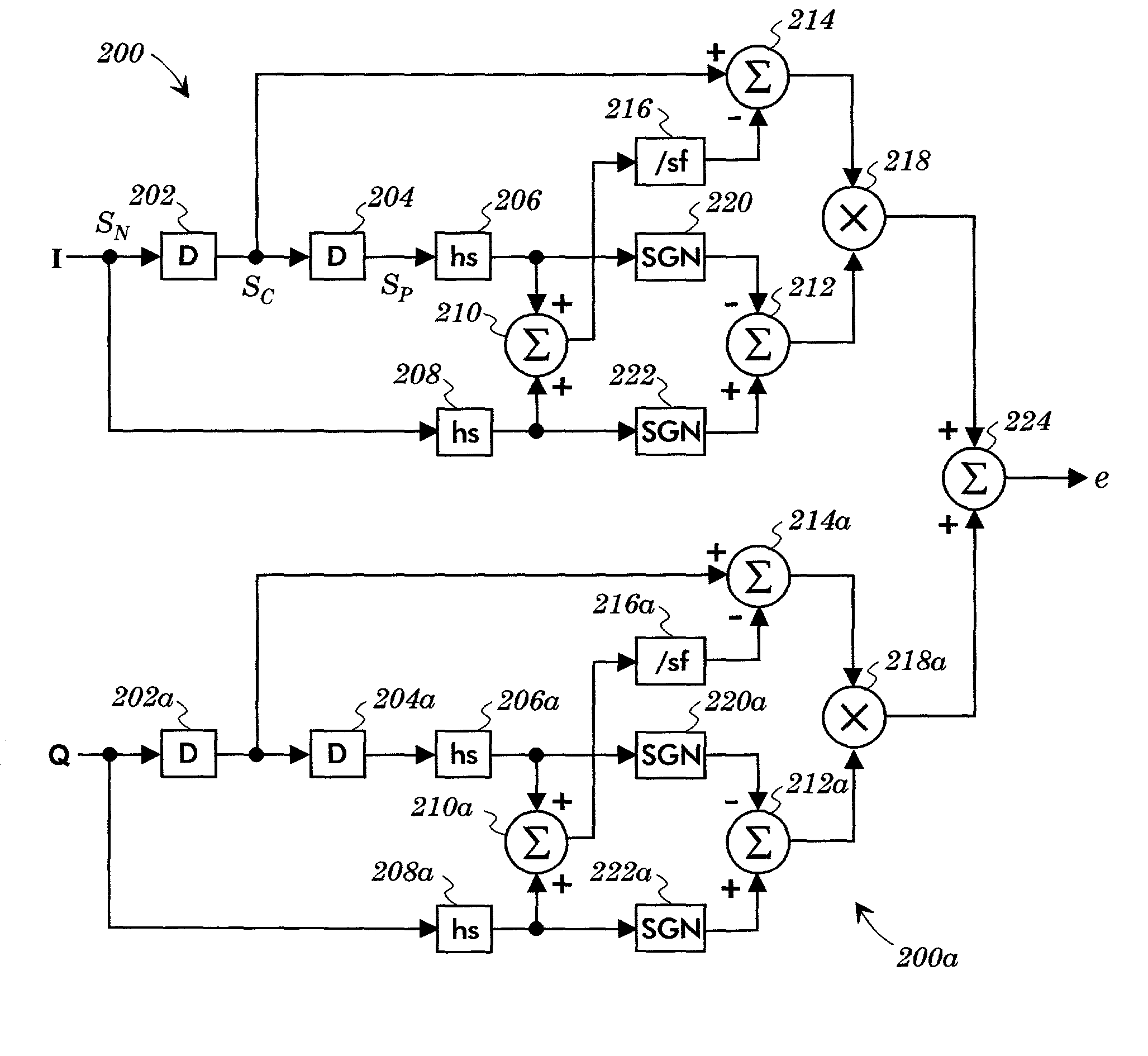
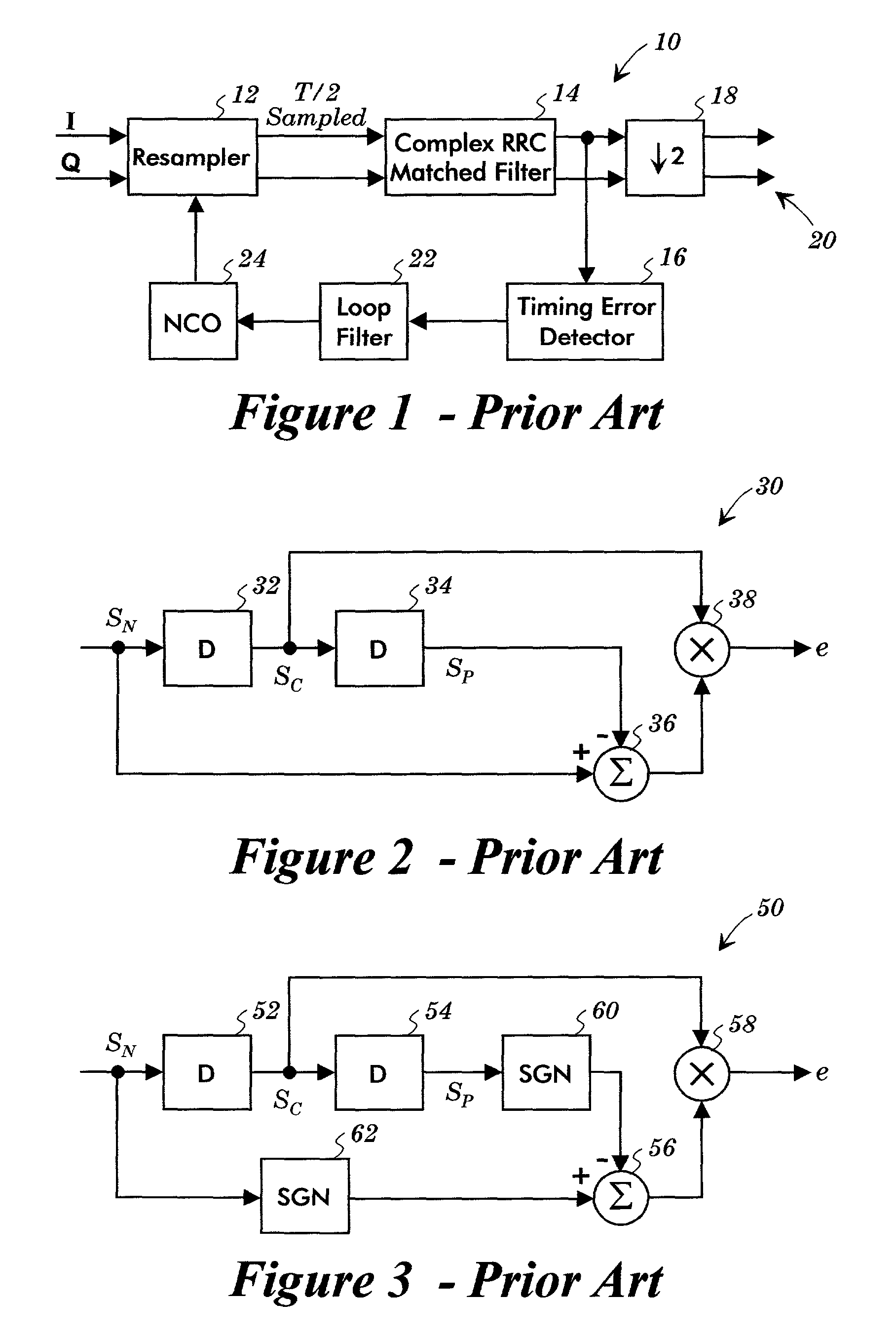
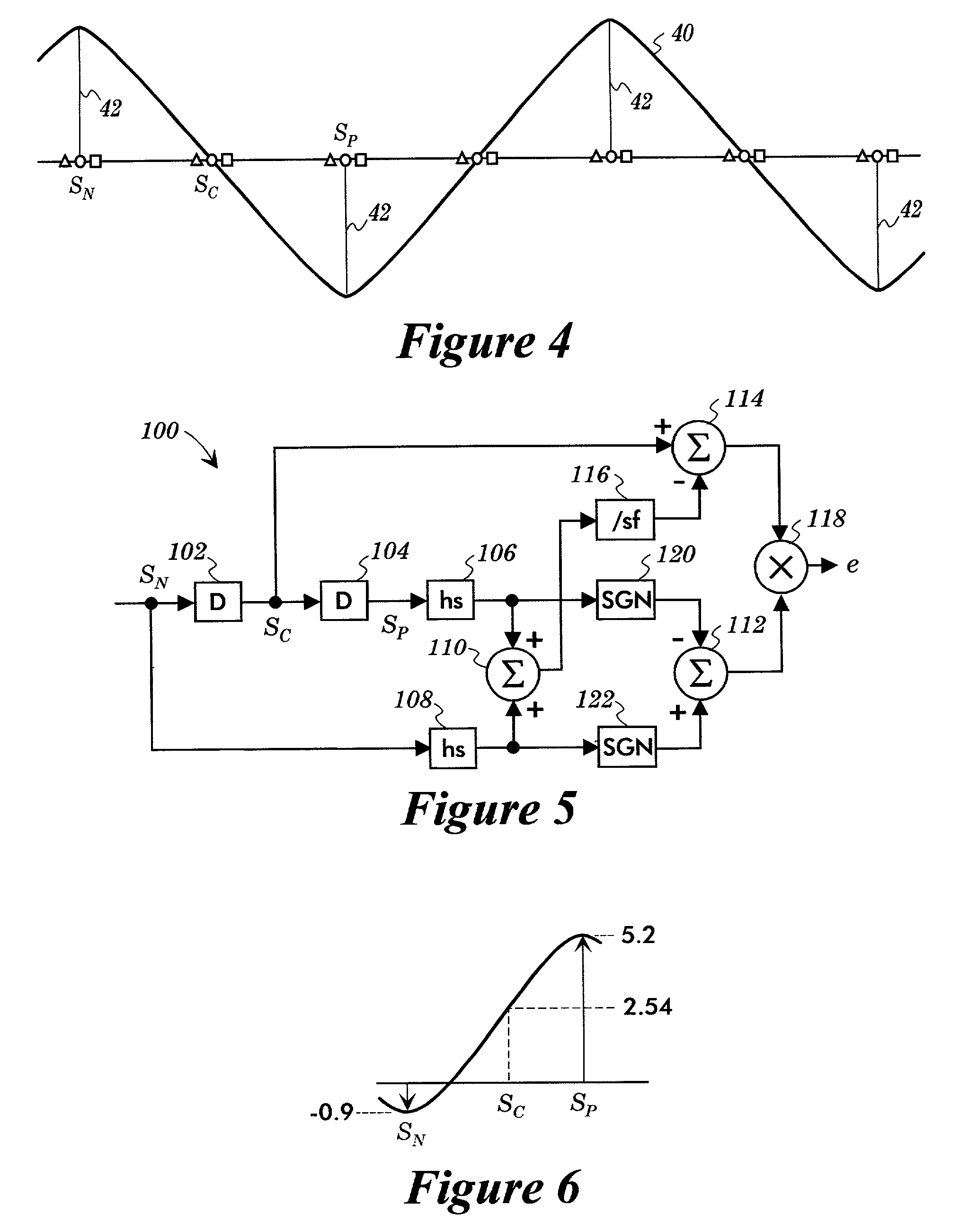
[0026]A timing error detector 100 according to one embodiment of the present invention is shown in FIG. 5. The timing error detector 100 is similar to the timing error detector 50 of FIG. 3 except that (i) hard slicers have been added to hard slice the samples SN and SP, and (ii) the sample SC is modified by an expression that includes a scaling factor sf.

[0027]Accordingly, the timing error detector 100 comprises two T / 2 delay elements 102 and 104, two hard slicers 106 and 108, three summers 110, 112, and 114, a scaling factor operator 116, a multiplier 118, and two sign operators 120 and 122. The timing error detector 100 receives th...


PUM


Abstract

A received signal having a series of T-spaced symbols having more than two levels is sampled at a rate that produces successive samples SP, SC, and SN substantially equally spaced by T/2. An output representing the difference between the sign of the sample SN and the sign of the sample SP is generated, and the value of the sample SC is offset so that the value of the sample SC approaches zero. The offset value of the sample SC and the generated output are multiplied together in order to provide a timing error signal. The sampling of the received signal is controlled in accordance with the timing error signal.

Description

TECHNICAL FIELD OF THE INVENTION[0001]The present invention relates to a timing error detector for a digital signal receiver.BACKGROUND OF THE INVENTION[0002]In digital receivers, it is important to obtain symbol synchronization by accurately sampling the received signal. A common technique to achieve accurate symbol sampling employs a timing error detector for controlling a numerically controlled oscillator in order to sample the received signal at the proper sampling times.[0003]A typical example of a digital receiver incorporating a timing error detector is depicted in FIG. 1 as a digital receiver 10. The I and Q components of a demodulated digital signal are supplied to a resampler 12 of the digital receiver 10. The resampler 12 samples the demodulated I and Q components at twice the symbol rate. Thus, the resampler 12 provides two over-sampled sequences of T / 2 sampled multibit symbol values (T=symbol period). The sampled signals are passed through a Root Raised Cosine (RRC) mat...

Claims


Application Information

Patent Timeline
IPC IPC(8): G11B5/00H04L7/033
CPCH04L7/0334H04L7/0335
Inventor KIM, JIN H.FIMOFF, MARKOZEN, SERDAR
Owner ZENITH RADIO CORP
Why Eureka
Try Eureka