Timing recovery controller and operating method thereof

A controller and timing technology used in digital transmission systems, electrical components, transmission systems, etc.

Inactive Publication Date: 2012-03-14
NOVATEK MICROELECTRONICS CORP
View PDF3 Cites 3 Cited by
  • Summary
  • Abstract
  • Description
  • Claims
  • Application Information

AI Technical Summary

Problems solved by technology

[0010] However, the timing recovery controller 10 in the prior art can only perform timing recovery when the data of the data sequence Data_s...

Method used


Image

  • Timing recovery controller and operating method thereof
  • Timing recovery controller and operating method thereof
  • Timing recovery controller and operating method thereof

Examples


Embodiment Construction

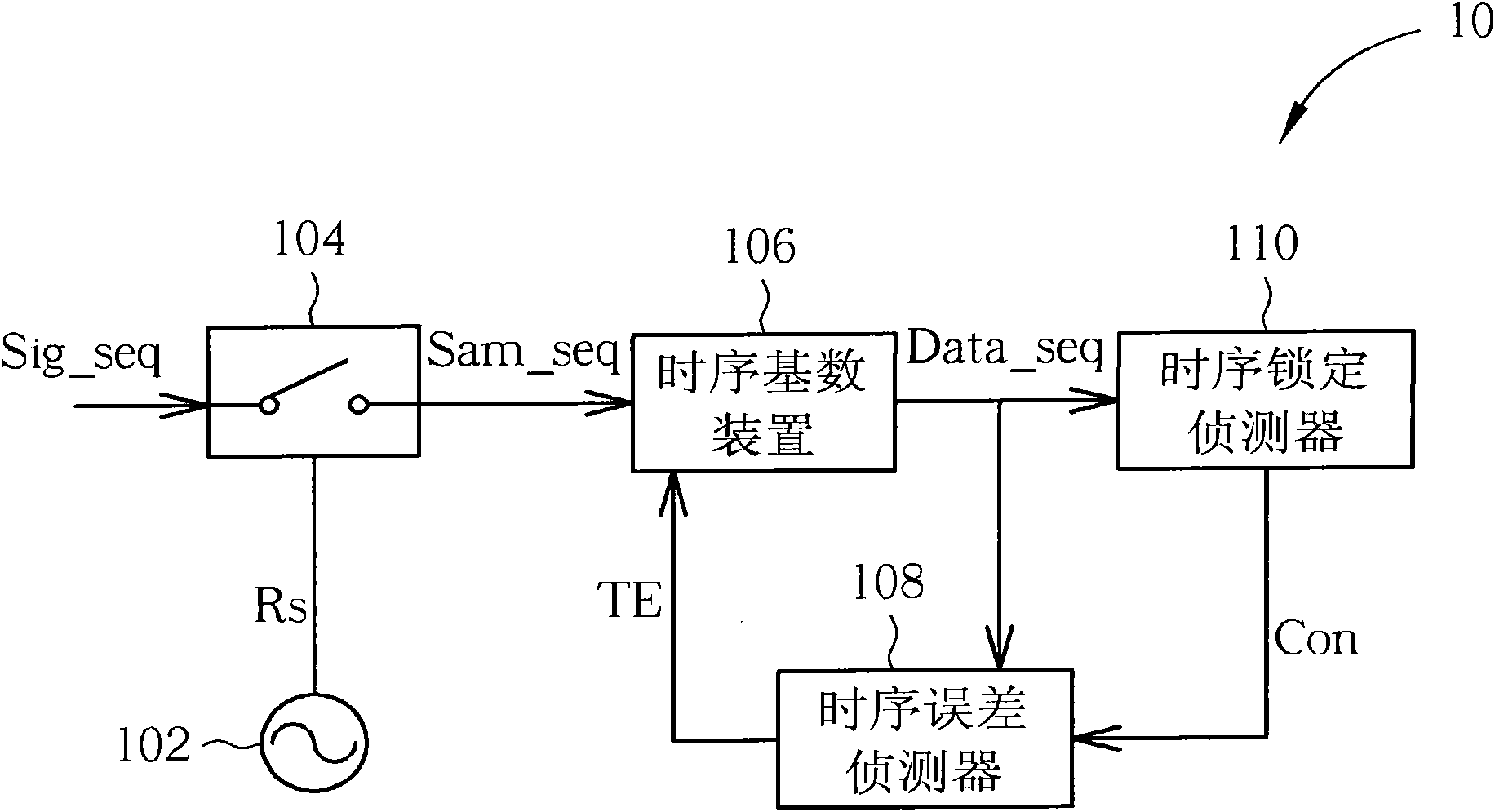
[0051] Please refer to Figure 4 , Figure 4 It is a schematic diagram of a timing recovery controller 40 according to an embodiment of the present invention. The structure and operating principle of the timing recovery controller 40 are partially similar to those of the timing recovery controller 10 , so components and signals with the same purpose use the same symbols for simplicity. The difference between the timing recovery controller 40 and the timing recovery controller 10 is that a timing error detector 408 and a timing lock detector 410 of the timing recovery controller 40 can be used for symbol data and instantaneous data in the data sequence Data_seq , the timing error value TE and the timing lock judgment result TL are respectively generated. In other words, the timing recovery controller 40 can perform timing recovery at twice the symbol rate (ie, the data rate) to speed up the timing recovery.

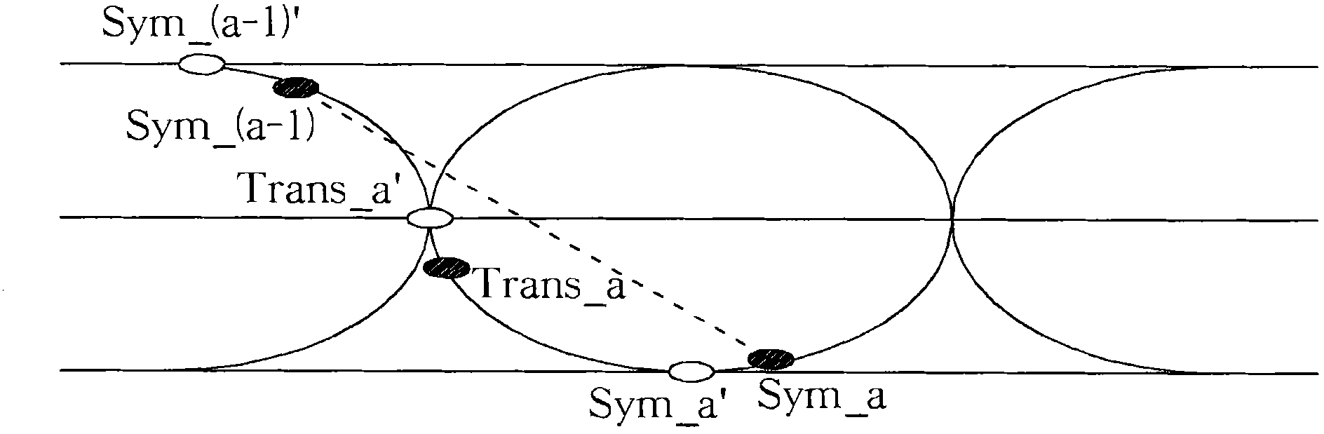
[0052] In detail, such as Figure 5A as shown, Figure 5A The ey...


PUM


Abstract

The invention discloses a timing recovery controller which can perform timing recovery at a doubled code rate. The timing recovery controller comprises a sampler, a timing base device, a timing error detector and a timing lock detector, wherein the timing error detector comprises a first delayer and a second delayer which are used for delaying signals to output a first delayed data sequence and a second delayed data sequence, and a timing error calculation module for generating a timing error value to adjust a timing base; and the timing lock detector comprises a third delayer for delaying a signal to output a third delayed data sequence, and a timing lock judgment module for generating a timing lock judgment result.

Description

technical field [0001] The present invention relates to a timing recovery controller, a timing error detector, a timing error detection method, a timing lock detector and a timing locking detection method, especially a timing recovery that can perform timing recovery at twice the symbol rate A recovery controller and its timing error detector, a timing error detection method, a timing lock detector and a timing lock detection method. Background technique [0002] In the field of digital communication, the signal transmitter (transmitter) sends a signal sequence carrying symbol data at a specific transmission rate, and the signal receiver (receiver) will sample the signal sequence at a sampling rate after receiving the data sequence. A sampling sequence is generated to restore symbol data according to a timing base. For example, if the sampling rate is 90MB and the timing base is 2, a data sequence with a data rate of 45MB can be obtained, wherein the data sequence includes ...

Claims


Application Information

Patent Timeline
IPC IPC(8): H04L7/00
CPCH04L7/0029
Inventor 黄共镳
Owner NOVATEK MICROELECTRONICS CORP
Why Eureka
Try Eureka