System and method for timing recovery in a discrete multi-tone system

a multi-tone system and timing recovery technology, applied in the field of communication systems, to achieve the effect of minimizing phase offsets in pilot ton

Inactive Publication Date: 2006-01-10
IKANOS COMMUNICATIONS
View PDF7 Cites 47 Cited by
  • Summary
  • Abstract
  • Description
  • Claims
  • Application Information

AI Technical Summary

Benefits of technology

[0024]In a preferred embodiment, a carefully chosen scrambler seed is used in generating the C-REVERB, C-SEGUE, and C-MEDLEY signals in the transmitter such that the phase offsets in the pilot tone are minimized.
[0029]The present invention can also be viewed as providing a method for reducing pilot tone phase interference during initialization and show time at the receiver in a discrete multi-tone (DMT) communications system. A first method focuses on generating a set of signals at the ATU-C that will result in significant reduction of the pilot tone phase interference when the cyclic prefix is added. In this regard, the method can be summarized by the following steps: generating C-REVERB, C-SEGUE, and C-MEDLEY with the pseudo-random pattern generator as specified by the ADSL standard but using an initial seed different from that specified by the standard when transmitting the three signal types in the DMT standard initialization sequence. A good seed has been found to be 90 (00101 1010 in binary, or 0x05A in hexadecimal), which results in phase offset of approximately 0.01° for C-REVERB and C-SEGUE.

Problems solved by technology

Timing recovery is necessary because the exact frequency and phase of the ATU-C is not known beforehand at the ATU-R and because the sampling clock at the ATU-C itself cannot be made exact due to variations in physical devices.

Method used


Image

  • System and method for timing recovery in a discrete multi-tone system
  • System and method for timing recovery in a discrete multi-tone system
  • System and method for timing recovery in a discrete multi-tone system

Examples


Embodiment Construction

[0050]Having summarized various aspects of the present invention, reference will now be made in detail to the description of the invention as illustrated in the drawings. While the invention will be described in connection with these drawings, there is no intent to limit it to the embodiment or embodiments disclosed therein. On the contrary, the intent is to cover all alternatives, modifications and equivalents included within the spirit and scope of the invention as defined by the appended claims.

[0051]It will be apparent to one of ordinary skill in the art that the present invention can be applied across the spectrum of digital subscriber line (DSL) systems or any communication system using the DMT or orthogonal frequency division modulation (OFDM). To reflect applicability across the multitude of DSL services, hereinafter, reference to DSL equipment and services will be designated xDSL.

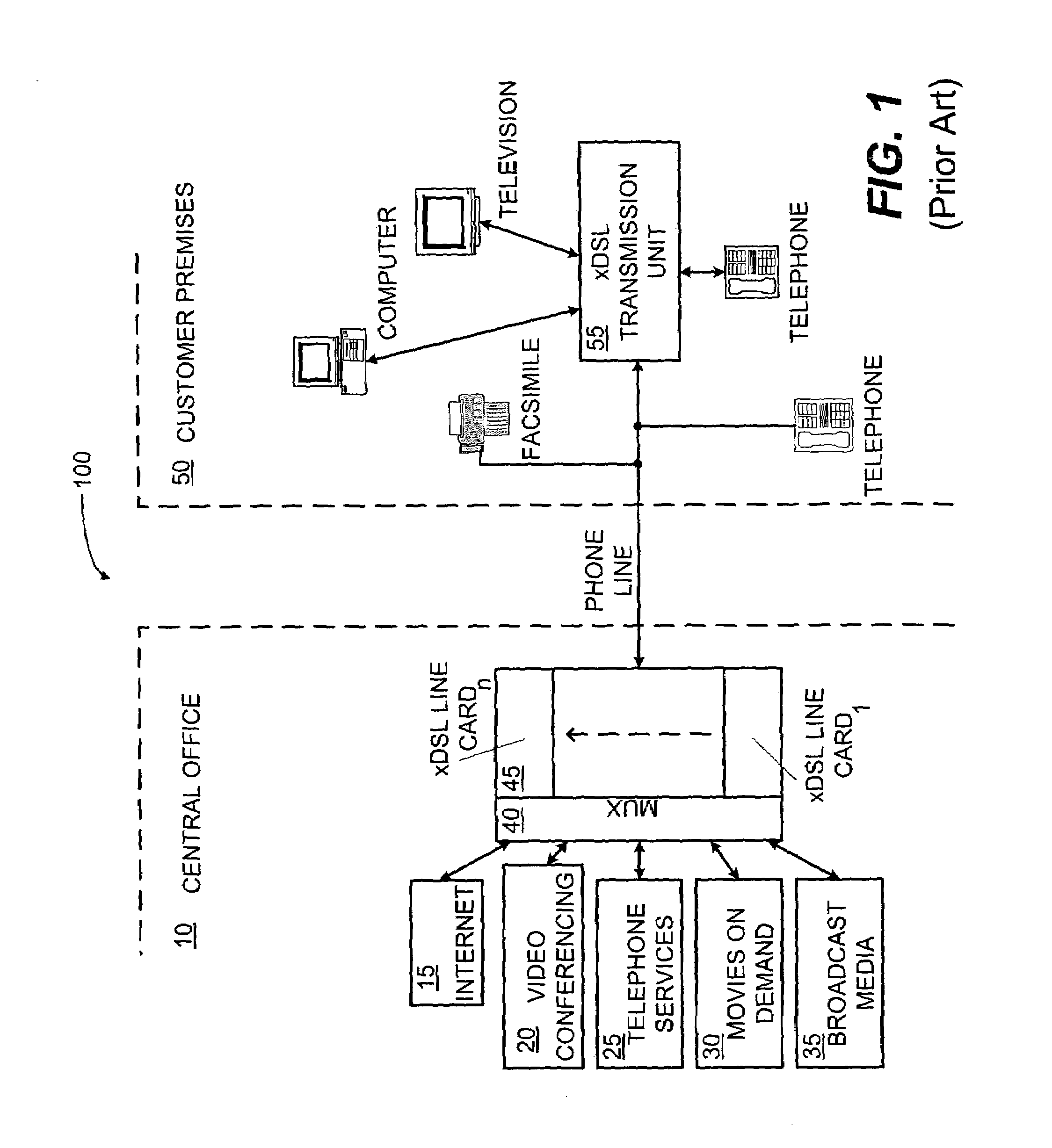
[0052]Turning now to the drawings, reference is made to FIG. 1, which illustrates the delivery ...


PUM


Abstract

A system and method for performing pilot tone based timing recovery in a communication system using the discrete multi-tone (DMT) modulation. In DMT modulation, interference is introduced to the phase of the pilot tone in the transmitter due to the cyclic prefix. Broadly, a receiver is configured to detect and apply a phase offset to the pilot tone in a phase locked-loop upon recognition of far-end signal segments during transceiver initialization. The output of the phase locked-loop is then used to control the timing of the analog-to-digital (A / D) and digital-to-analog (D / A) conversions. In alternative embodiments, the receiver is configured to detect and remove the cyclic prefix from the far-end signal either prior to, or after, time-domain equalization. In a similar manner, the resulting signal stream is applied to the input of the timing recovery phase locked-loop (PLL). The output of the PLL is used to control the timing of the A / D and D / A converters. In a further alternative embodiment, a phase error on the pilot tone is estimated in the frequency domain. The phase error is then applied to the input of a modified timing recovery PLL to reduce phase interference on the pilot tone.

Description

CROSS-REFERENCE TO RELATED APPLICATION[0001]The present application claims the benefit of U.S. provisional patent application Ser. No. 60 / 118,358, filed Feb. 3, 1999, which is hereby incorporated by reference in its entirety.BACKGROUND OF THE INVENTION[0002]1. Field of the Invention[0003]The present invention generally relates to communication systems, and more particularly, to a system and method for timing recovery in digital subscriber line (DSL) communication systems using the discrete multi-tone (DMT) modulation and standard.[0004]2. Discussion of the Related Art[0005]In recent years, telephone communication systems have expanded from traditional plain old telephone system (POTS) communications to include high-speed data communications as well. As is known, POTS communications include the transmission of voice information, control signals, PSTN (public switched telephone network) information, as well as, information from ancillary equipment in analog form (i.e. computer modems ...

Claims


Application Information

Patent Timeline
IPC IPC(8): H04L7/00
CPCH04L27/2675H04L27/2662H04L7/0083H04L7/065H04L2025/03414
Inventor JABBAR, FAROOQLANGBERG, EHUDLIU, WEIMIN
Owner IKANOS COMMUNICATIONS
Why Eureka
Try Eureka