
Method and apparatus for measuring wall thickness of plastic container

Inactive Publication Date: 2006-01-10
PLASTIC TECH INC
View PDF24 Cites 24 Cited by
  • Summary
  • Abstract
  • Description
  • Claims
  • Application Information

AI Technical Summary

Benefits of technology

[0007]An object of the invention is to produce a plastic container wall thickness measuring system which minimizes production costs.
[0008]Another object of the invention is to produce a plastic container wall thickness measuring system, which minimizes product waste.
[0009]Still another object of the invention is to produce a plastic container wall thickness measuring system which minimizes production line downtime.
[0010]Another object of the invention is to produce a plastic container wall thickness measuring system, which can operate on-line and at a high speed during a plastic container manufacturing process.
[0011]A further object of the invention is to produce a plastic container wall thickness measuring system which can measure through both walls of the container simultaneously, and determine the average wall thickness by dividing the measurement by two.
[0012]Yet another object of the invention is to produce a plastic container wall thickness measuring system, which can make multiple thickness measurements at a given height on the container.
[0013]Still another object of the invention is to produce a plastic container wall thickness measuring system, which can make multiple thickness measurements from multiple heights on the container.

Problems solved by technology

One of the difficulties in blow molding plastic containers is the problem of maintaining uniform wall thickness throughout the height of the container.
Even with well made preforms, slight deviations from ideal temperature distribution in the preform can cause nonuniformity and thin areas or regions in the sidewalls.
Because of this problem it is usually necessary to use more resin than is needed theoretically in order to maintain minimum wall thickness specifications, resulting in higher production costs.
For example, if one area of the sidewall is running too thick, the additional thickness can indicate that some other area where the wall thickness is difficult to measure, such as the heel, is running too thin.
If the manufacturing process is out of specification limits, a large quantity of scrap can be generated before the necessary information can be acquired and a correction made.
The sectioning and manual measurement of the wall thickness distribution can be tedious, time consuming, and inaccurate.
Consequently, the manufacturing process results in a large variation in container wall thickness, rarely approaching the optimum distribution necessary for achieving a desired minimum weight of the final product.
However, these generally require the container to be removed from the manufacturing machine, loaded upon or within the measuring system, and a large number of measurements made off-line.
These systems are normally found in the quality control laboratory and cannot provide timely feedback to the forming process.

Method used


Image

  • Method and apparatus for measuring wall thickness of plastic container
  • Method and apparatus for measuring wall thickness of plastic container
  • Method and apparatus for measuring wall thickness of plastic container

Examples


Embodiment Construction

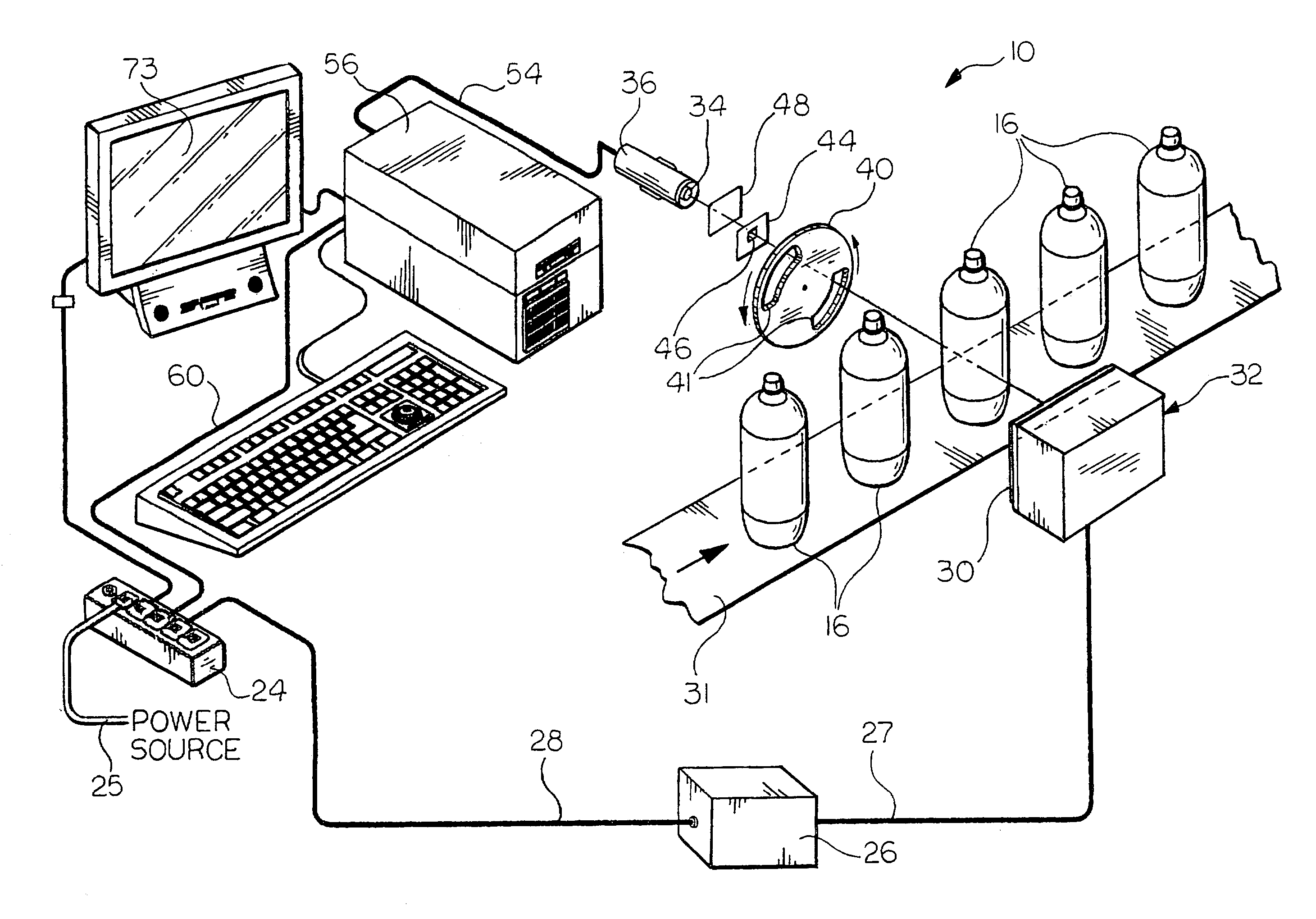
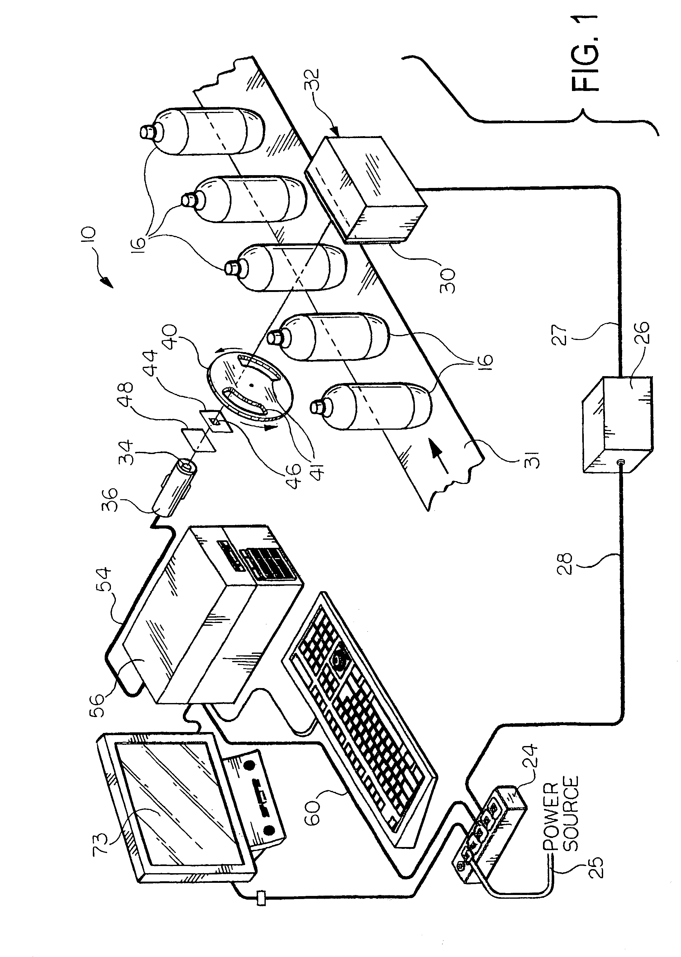
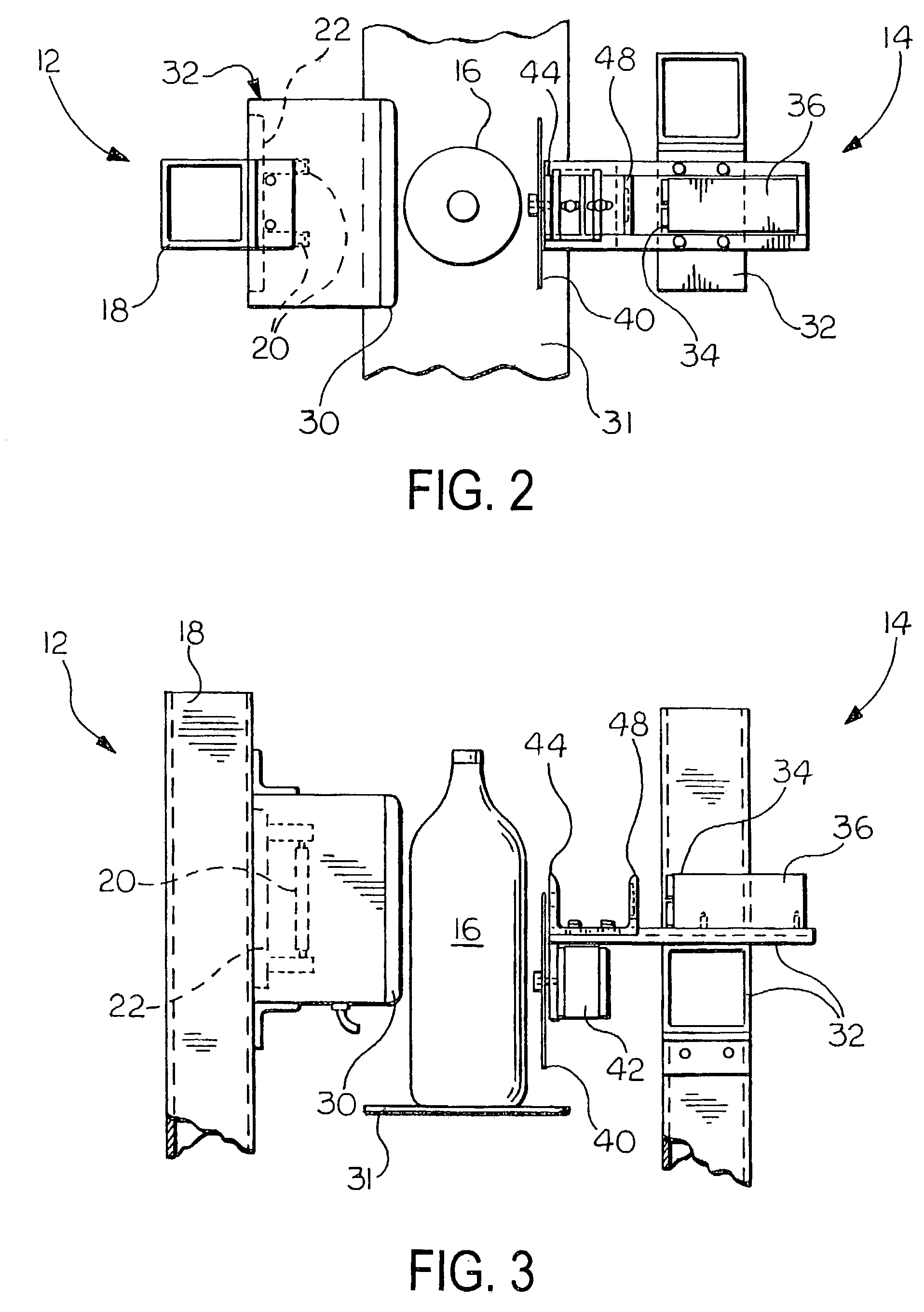
[0023]Referring now to the drawings, and particularly FIG. 1, there is shown generally at 10 a plastic container wall thickness measuring system incorporating the features of the invention. Referring now to FIGS. 2 and 3, the wall thickness measuring system 10 includes an emitter assembly 12 and a sensor assembly 14. The emitter assembly 12 and sensor assembly 14 are spaced apart such that a plastic container 16, such a polyethylene terephthalate (PET), blow molded bottle, can be caused to travel there between.

[0024]The emitter assembly 12 includes a first support frame 18 made of a rigid material such as aluminum. The support frame 18 is configured for engagement with any suitable surface, such as a floor, and an associated plastic container manufacturing machine (not shown).

[0025]The emitter assembly 12 further includes at least one incandescent light bulb 20 for emitting light energy with a majority of the light energy output occurring in the infrared (IR) frequency range. Prefer...


PUM

PropertyMeasurementUnit
Temperatureaaaaaaaaaa
Fractionaaaaaaaaaa
Areaaaaaaaaaaa

Abstract

A method for measuring the wall thickness of plastic containers (16) during a container manufacturing process includes providing a plastic container (16), the plastic container (16) having a longitudinal axis and at least two side walls spaced radially from the longitudinal axis. The side walls are formed of a material that absorbs light energy in a predetermined molecular absorption band. Light energy is then directed from a source unit (32) through the at least two side walls of the plastic container (16) in a plane transverse to the longitudinal axis of the plastic container (16). A portion of the light energy that passes through the sidewalls of the container (16) is sensed by a sensor (34), and a signal representing a thickness of the sidewalls of the plastic container is generated from the sensed portion of the energy by a computer (56).

Description

RELATED APPLICATIONS[0001]This application claims the benefit of U.S. provisional application Ser. No. 60 / 186,188, filed Mar. 1, 2000.FIELD OF THE INVENTION[0002]The present invention relates to a method and apparatus for measuring wall thickness, and more particularly to a method and apparatus for measuring the wall thickness of plastic containers at the production line and during the production operation.BACKGROUND OF THE INVENTION[0003]One of the difficulties in blow molding plastic containers is the problem of maintaining uniform wall thickness throughout the height of the container. Even with well made preforms, slight deviations from ideal temperature distribution in the preform can cause nonuniformity and thin areas or regions in the sidewalls. Because of this problem it is usually necessary to use more resin than is needed theoretically in order to maintain minimum wall thickness specifications, resulting in higher production costs.[0004]Currently, it is necessary for someon...

Claims


Application Information

Patent Timeline
IPC IPC(8): G01B11/06B29C49/78
CPCB29C49/78B29K2067/00B29L2031/7158G01B11/06B29C49/6835B29C2049/7871B29C2049/78805
Inventor SEMERSKY, FRANK E.STURGILL, DENNIS T.
Owner PLASTIC TECH INC
Learn More