
Plasma processor in plasma confinement region within a vacuum chamber

Inactive Publication Date: 2006-01-10
LAM RES CORP
View PDF16 Cites 62 Cited by
  • Summary
  • Abstract
  • Description
  • Claims
  • Application Information

AI Technical Summary

Benefits of technology

[0011]One aspect of the invention relates to a vacuum plasma chamber for processing a workpiece wherein the chamber includes a reactive plasma excitation impedance element connected to a first, relatively high frequency RF plasma excitation source and an electrode for carrying the workpiece is connected to a second, relatively low frequency RF bias source. A filter arrangement connecte

Problems solved by technology

While the foregoing structures have been adequate for processing prior art workpieces, they are not believed to be adequate to handle deep submicron processing of workpieces, particularly semiconductor wafers meeting increased requirements for etching and deposition of films.
In addition, for workpieces ha

Method used


Image

  • Plasma processor in plasma confinement region within a vacuum chamber
  • Plasma processor in plasma confinement region within a vacuum chamber
  • Plasma processor in plasma confinement region within a vacuum chamber

Examples


Example

DETAILED DESCRIPTION OF THE DRAWING

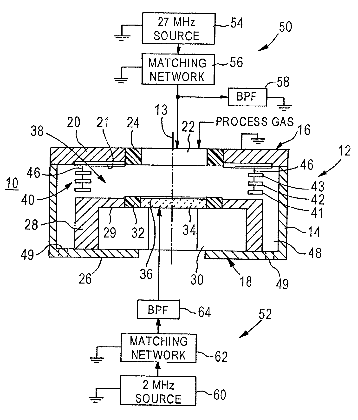
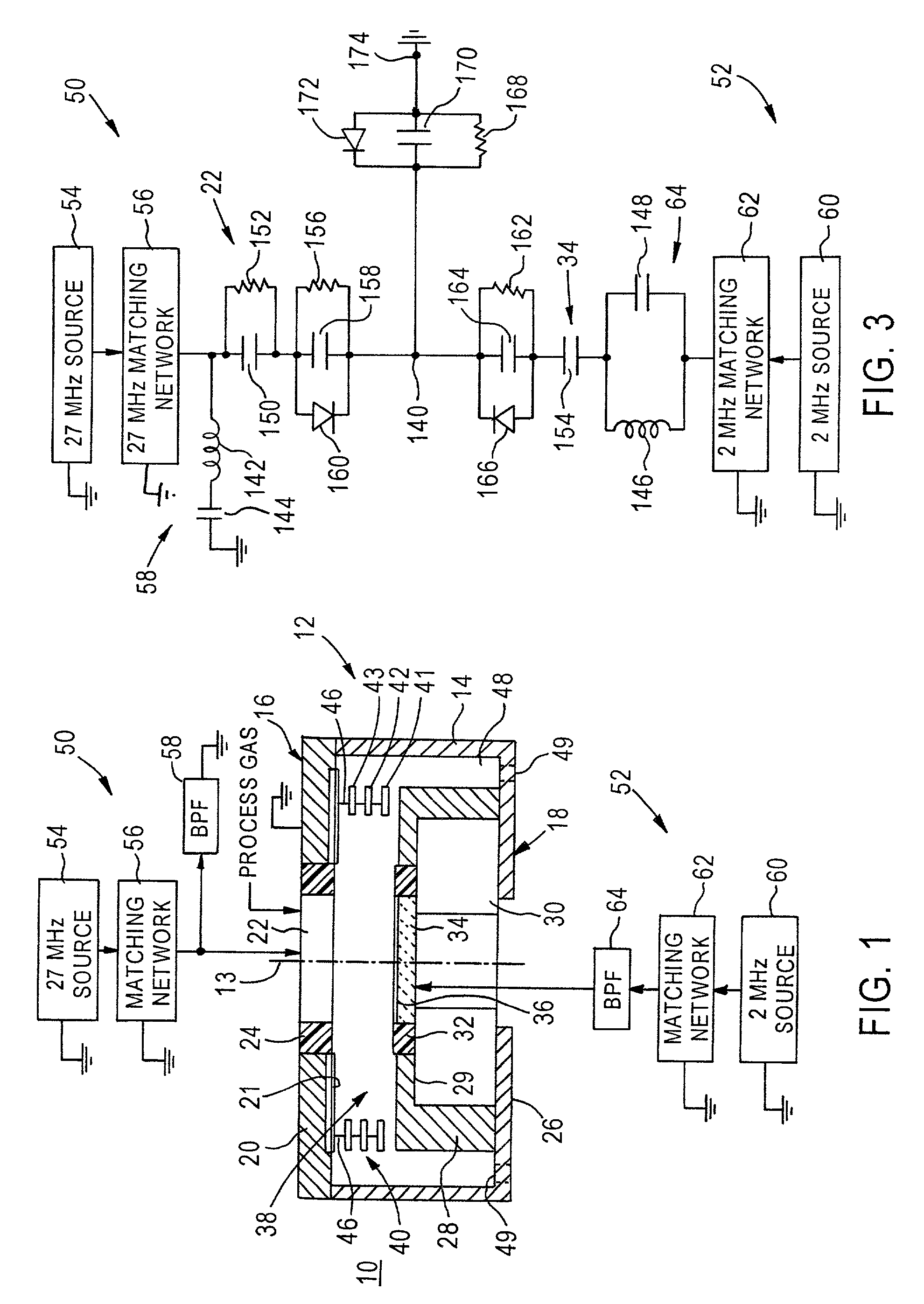
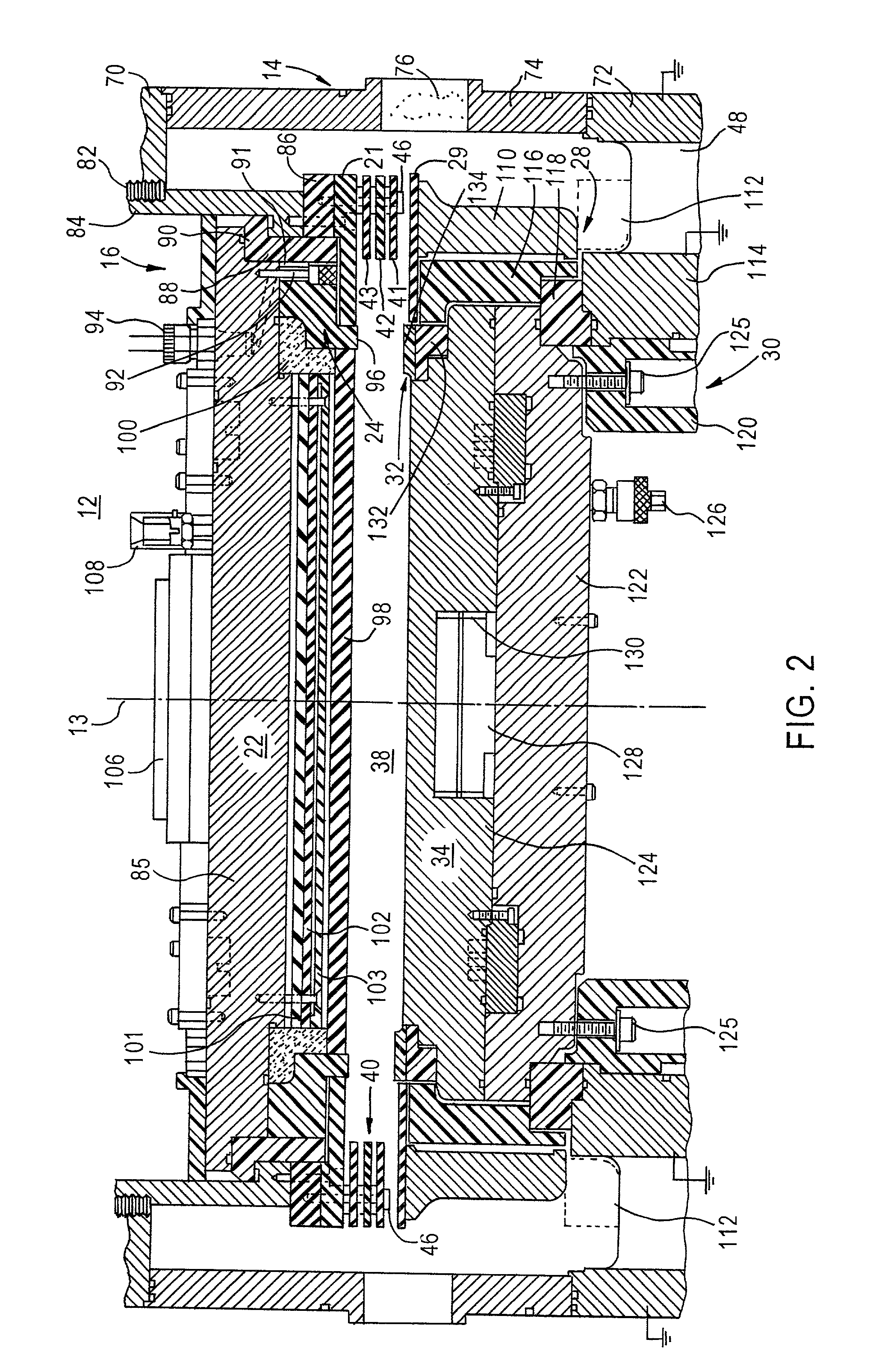
[0023]Reference is now made to FIG. 1 of the drawing wherein plasma processor 10 is illustrated as including vacuum chamber 12, preferably having a cylindrical configuration so that the chamber is symmetrical with respect to its central longitudinal axis 13. Chamber 12 includes high electrical conductivity cylindrical metal sidewall 14 maintained at RF and DC reference potential (e.g., ground), as well as circular ceiling 16 and circular base 18. Ceiling 16 includes annular exterior high electrical conductivity metal plate 20 which carries on its lower face high electrical conductivity ring 21. Plate 20 and ring 21 are electrically and mechanically connected to wall 14 so that plate 20 and ring 21 are also at RF and DC ground potential. Ceiling 16 also includes circular, metal electrode 22 (a plasma exciting reactive impedance element) and annular electric insulator 24 that separates and electrically insulates electrode 22 from plate 20. Plate 20, ...


PUM

PropertyMeasurementUnit
Electrical conductivityaaaaaaaaaa
Currentaaaaaaaaaa
Areaaaaaaaaaaa

Abstract

A vacuum plasma chamber for processing a workpiece includes first and second electrodes for electrical coupling with gas in the chamber and respectively connected to first and second relatively high and low frequency RF sources. The chamber includes a wall at a reference potential and a plasma confinement region spaced from the wall. A filter arrangement connected to the sources and the electrodes enables current from the first source to flow to the first electrode, prevents the substantial flow of current from the first source to the second electrode and the second source, and enables current from the second source to flow to the first and second electrodes and prevents the substantial flow of current from the second source to the first source.

Description

RELATION TO CO-PENDING APPLICATION[0001]The present application is a continuation-in-part of our commonly assigned provisional application Ser. No. 60 / 311,050, filed Aug. 8, 2001, entitled “Dual Frequency Plasma Etch Reactor with Independent Plasma Density / Chemistry and Ion Energy Control.”FIELD OF INVENTION[0002]The present invention relates generally to vacuum plasma processors and more particularly to a vacuum plasma processor including a plasma excitation region including first, second and third electrodes respectively connected to high and low frequency excitation sources and to a reference potential, wherein the excitation region is confined within a vacuum chamber having a wall at the reference potential. Another aspect of the invention relates to a vacuum plasma processor including a reactive impedance element and an electrode for respectively exciting a plasma in the a vacuum plasma processor with high and low frequency RF, wherein a filter arrangement in supply circuits fo...

Claims


Application Information

Patent Timeline
IPC IPC(8): H01L21/00C23C16/00H01J37/32
CPCH01J37/32082H01J37/32522Y10S156/916
Inventor DHINDSA, RAJINDERSRINIVASAN, MUKUNDLENZ, ERICLI, LUMIN
Owner LAM RES CORP
Learn More