
Method for carrying out an integrity test for filter elements

a filter element and integrity testing technology, applied in the field of integrity testing of filter elements, can solve the problems of inability to detect unacceptable increased gas flow, and inability to carry out integrity testing

Inactive Publication Date: 2006-01-10
SARTORIUS STEDIM BIOTECH GMBH
View PDF15 Cites 34 Cited by
  • Summary
  • Abstract
  • Description
  • Claims
  • Application Information

AI Technical Summary

Benefits of technology

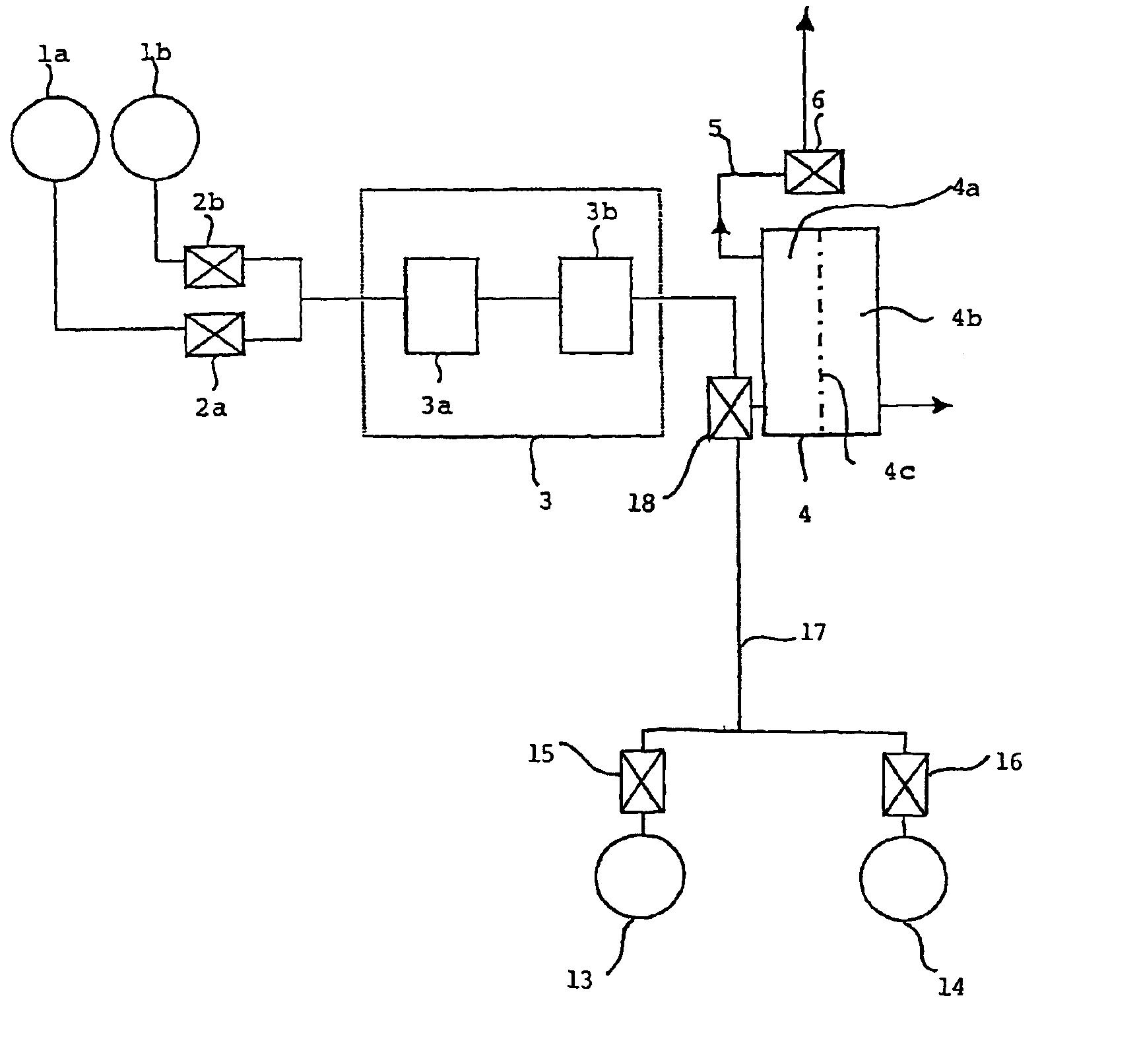
The present invention provides an improved method for testing the integrity of filter elements in a device. The method distinguishes between gas flow caused by diffusion through a wetting liquid and convection caused by large pores or defects in the filter material. This allows for a more accurate assessment of the integrity of the filter elements, even if they have a large area. The method uses two different test gases and two different wetting liquids, and measures the volumetric gas flow rate at different pressures and temperatures. The ratio of the solubility and diffusion coefficients of the test gas in the wetting liquid at the test pressure and temperature is determined to determine the convection component of the volumetric gas flow rate. This allows for a more definitive assessment of the integrity of the filter elements.

Problems solved by technology

This is no longer possible, however, in large area systems with many filter elements connected in parallel or with large filter cartridges that currently have filter areas of up to 90 m2.
This method has the drawback that the desired inference is not unambiguous since, in such a case, defective filter elements may be present in the filter housing but their unacceptable increased gas flow cannot be detected by the collective measurement of the total flow rate.
If, however, the measured total flow rate exceeds the first desired flow rate by an amount that is greater than the amount allowed by the first predefined range, this should mean that at least one filter element is not intact.
This procedure again has the drawback that this inference, too, is not unambiguous, since in such a case defective filter elements may be present in the non-blocked segments but their unacceptably increased gas flow rate cannot be detected by the collective measurement of the flow rate.
Thus, the method proposed by U.S. Pat. No. 5,417,101 does not produce unambiguous results with respect to the integrity of the filter elements.

Method used


Image

  • Method for carrying out an integrity test for filter elements
  • Method for carrying out an integrity test for filter elements
  • Method for carrying out an integrity test for filter elements

Examples


example 1

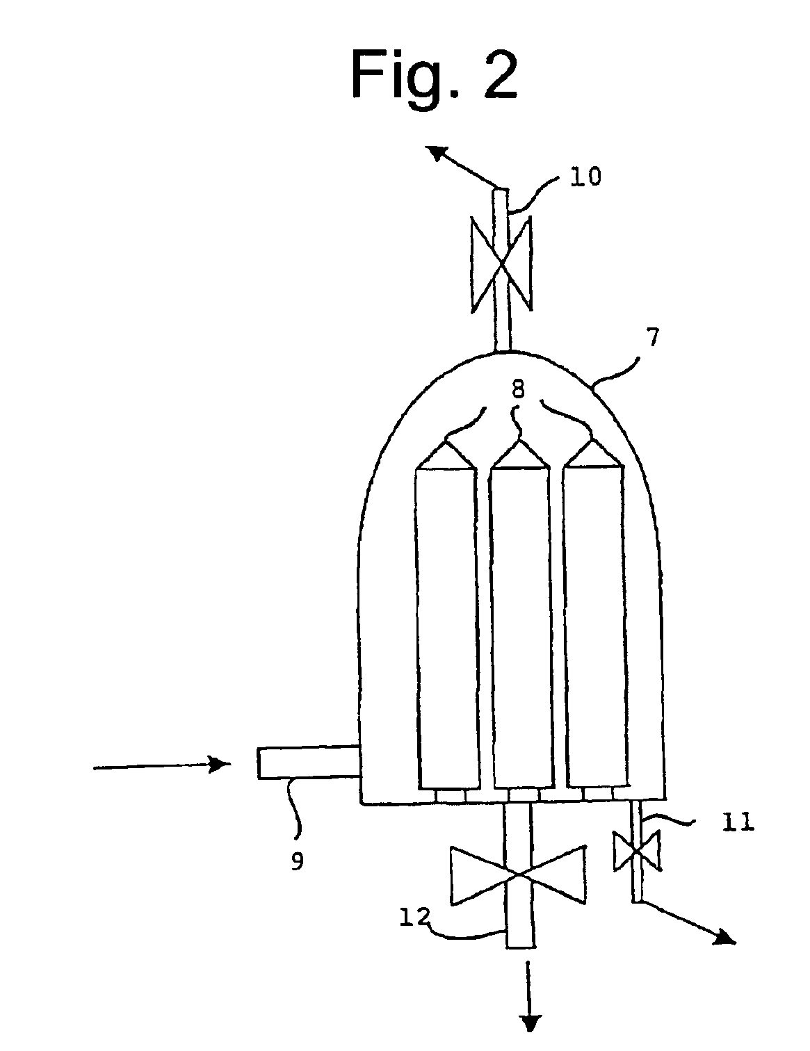
[0090]The method according to the invention was carried out by means of diffusion measurements at a test pressure of 1 bar using four separate Sartocon-II cassettes made by Sartorius AG. The membrane of cassette No. 4 was mechanically damaged. The test gases used were air and CO2. Furthermore, the same measurements were simultaneously made with three intact cassettes (No. 1-3), again with air and CO2. Finally, the method was simultaneously carried out using two intact (No. 1 and No. 2) and one intentionally damaged cassette (No. 4) under the same test conditions, again using air and CO2 as test gases. The device used to control the pressure and to determine the gas volume was a Sartocheck-3-EPS type device (Sartorius AG). The filter cassettes were cross flow units of the type 3021442906E-SG (Sartorius AG). Each filter cassette had a total membrane area of 0.6 m2.

[0091]The measuring parameters are given in Table 2. The measuring time differs because the optimal operating range of the...

example 2

[0097]The method according to the invention was carried out with three separate Sartorius AG Sartocon-II cassettes by means of diffusion measurements at a test pressure of 0.5 bar. The membrane of cassette No. 3 was mechanically damaged. The test gas used was air and the wetting liquids were ethanol (96%) and water. The same measurements were conducted simultaneously with two intact cassettes (No. 1-2), again using ethanol (96%) and water. The method was then carried out simultaneously with one intact cassette (No. 2) and one deliberately damaged cassette (No. 3) under the same test conditions, again using ethanol (96%) and water as wetting liquids. Finally, the method was carried out simultaneously with two intact cassettes (Nos. 1 and 2) and one deliberately damaged cassette (No. 3) under the same test conditions, again using ethanol (96%) and water as wetting liquids. The device used to control the pressure and to determine the gas volume was a Sartocheck-3-EPS type device (Sarto...


PUM

PropertyMeasurementUnit
areaaaaaaaaaaa
areasaaaaaaaaaa
volumetric gas flow rateaaaaaaaaaa

Abstract

A method for testing the integrity of filter elements, in which the convective component of the volumetric gas flow rate is determined from the ratio of the volumetric gas flow rates and the ratio of the solubility or diffusion coefficients of two different gases in the wetting liquid of the filter elements or is determined from the ratio of the volumetric gas flow rates and the ratio of the solubility or diffusion coefficients of a test gas in two different wetting liquids.

Description

CROSS REFERENCE TO RELATED APPLICATIONS[0001]This application is a continuation of international patent application no. PCT / EP02 / 03386, filed Mar. 26, 2002, designating the United States of America, and published in German as WO 02 / 078823, the entire disclosure of which is incorporated herein by reference. Priority is claimed based on Federal Republic of Germany patent application no. DE 101 16,335.5, filed Apr. 2, 2001.BACKGROUND OF THE INVENTION[0002]The present invention relates to a method for testing the integrity of filter elements.[0003]Filtration systems, particularly those for sterile filtration, are tested for their integrity prior to and after filtration to ensure filtration reliability and product safety. This includes a diffusion test, a pressure retention test and a bubble point test, which are also approved for use in pharmaceutical applications, with special safety requirements regarding sterile filtration. These tests correlate to destructive load tests, the so-call...

Claims


Application Information

Patent Timeline
Patent Type & Authority Patents(United States)
IPC IPC(8): G01N15/08B01D65/10
CPCB01D65/104
Inventor GRUMMERT, ULRICHPAHL, INA
Owner SARTORIUS STEDIM BIOTECH GMBH
Learn More