
Exhaust gas control device-equipped internal combustion engine and exhaust gas control method

a technology of exhaust gas control device and internal combustion engine, which is applied in the direction of electrical control, exhaust treatment electric control, separation process, etc., can solve the problems of diesel engine exhaust gas, particulate matter produced not only from diesel engines, and direct injection type gasoline engines are apt to produce smoke, so as to achieve the effect of more efficient removal of particulate matter

Inactive Publication Date: 2005-12-27
TOYOTA JIDOSHA KK
View PDF24 Cites 28 Cited by
  • Summary
  • Abstract
  • Description
  • Claims
  • Application Information

AI Technical Summary

Benefits of technology

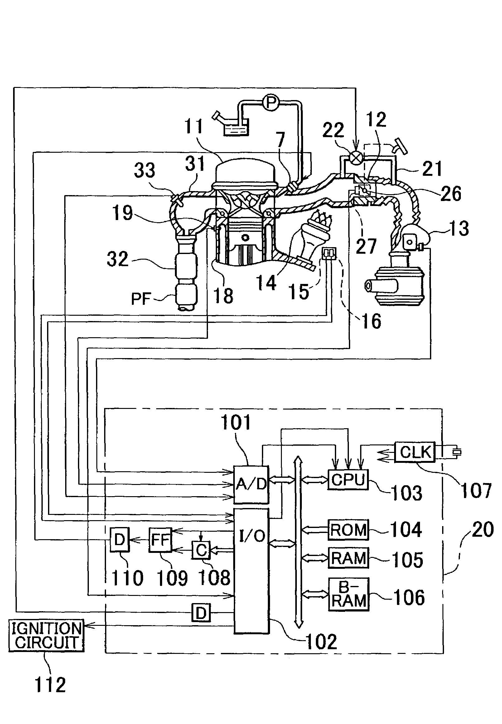
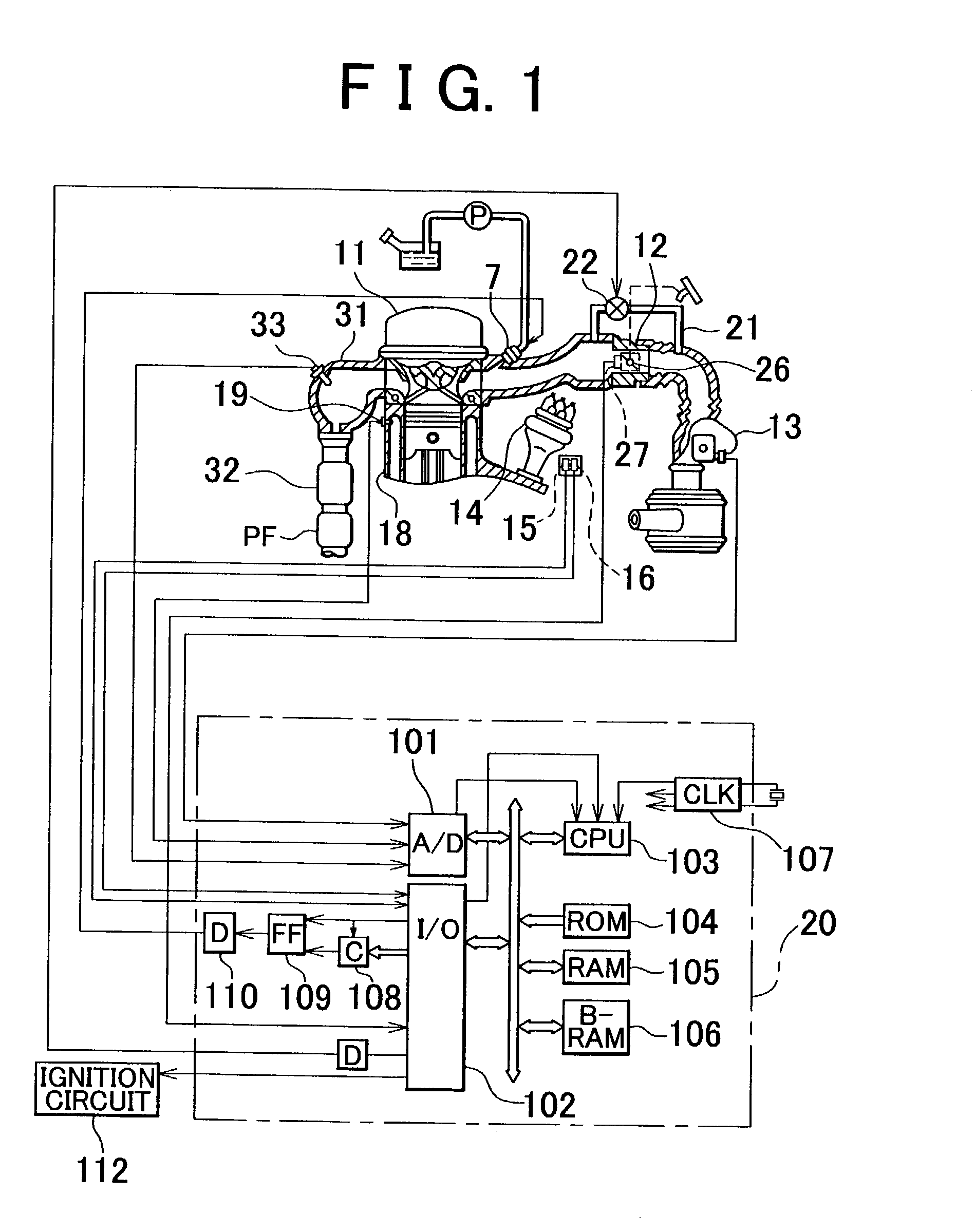
The invention aims to improve the removal of particulate matter produced by gasoline engines. It proposes a method where the air-fuel ratio is shifted to a leaner side to increase the supply of oxygen, which helps to oxidize the particulate matter. This is achieved by using an air-fuel ratio controller that can change between a feedback control towards a stoichiometric air-fuel ratio and a feedback control towards a lean-burn combustion side based on the state of particulate matter in the exhaust gas control device. The internal combustion engine may also include a first air-fuel ratio controller for performing a stoichiometric feedback control and a second air-fuel ratio controller for performing a lean feedback control, where the second controller takes over when the particulate matter level is high. The technical effect of this invention is to improve the efficiency of particulate matter removal in gasoline engines.

Problems solved by technology

Particulate matter in engine exhaust gas, including small particles of soot, and the like, is typically a problem in diesel engines.
However, particulate matter is produced not only from diesel engines, but also from gasoline engines.
In particular, direct-injection type gasoline engines are apt to produce smoke due to excessively high fuel concentration near ignition plugs during a stratified lean combustion mode in which a small amount of fuel provided in a stratified state in combustion chambers is burned.

Method used


Image

  • Exhaust gas control device-equipped internal combustion engine and exhaust gas control method
  • Exhaust gas control device-equipped internal combustion engine and exhaust gas control method
  • Exhaust gas control device-equipped internal combustion engine and exhaust gas control method

Examples


example 4

OF DETERMINATION

[0107]The aforementioned determination is made if it is determined that the particulate matter oxidation speed is low, by considering the particulate matter oxidation speed from the amount of particulate matter discharged and the temperature. It is determined that the particulate matter oxidation speed is low as the amount of particulate matter discharged increases, and as the temperature decreases.

[0108]b) If a clogged state of a particulate matter filter is detected, the feedback control is set toward the lean side by a technique described above.

example 1

OF DETECTION OF CLOGGING

[0109]The aforementioned determination is made if a pressure sensor detects a pressure rise above a threshold.

example 2

OF DETECTION

[0110]The aforementioned determination is made if the degree of decrease in the amount of intake air exceeds a threshold.


PUM

PropertyMeasurementUnit
crank angleaaaaaaaaaa

Abstract

In an exhaust gas control device-equipped internal combustion engine, particulate matter produced in conjunction with combustion of gasoline in a combustion chamber is oxidized by an exhaust gas control device provided in an exhaust passage. The engine includes air-fuel ratio control changer that changes between a feedback control toward a stoichiometric air-fuel ratio whereby an amount of oxygen in exhaust gas is reduced and a feedback control toward a lean-burn combustion side whereby the amount of oxygen in exhaust gas is increased, if the oxidation speed of particulate matter in the exhaust gas control device provided in the exhaust passage is slow, or if the amount of deposit of particulate matter is great.

Description

INCORPORATION BY REFERENCE[0001]The disclosure of Japanese Patent Application No. 2002-7682 filed on Jan. 16, 2002, including its specification, drawings and abstract, is incorporated herein by reference in its entirety.BACKGROUND OF THE INVENTION[0002]1. Field of the Invention[0003]The invention relates to a control of particulate matters produced from an internal combustion engine and, more particularly, from a gasoline engine.[0004]2. Description of the Related Art[0005]Particulate matter in engine exhaust gas, including small particles of soot, and the like, is typically a problem in diesel engines. Various technologies for removing particulate matter from diesel engine exhaust gas have been developed. Such a technology is disclosed in, for example, Japanese Examined Patent Application Publication No. 7-106290.[0006]However, particulate matter is produced not only from diesel engines, but also from gasoline engines. In particular, direct-injection type gasoline engines are apt t...

Claims


Application Information

Patent Timeline
Patent Type & Authority Patents(United States)
IPC IPC(8): B01D46/42F02D45/00F01N3/02F01N3/023F01N3/035F01N3/08F01N3/24F01N9/00F01N13/02F02B75/12F02D41/02F02D41/14
CPCF01N3/0842F02D41/029F02D41/1474F02D41/1483F02D41/1495F02D41/2461F01N13/0097F01N13/009F01N3/0231F01N3/035F01N3/0814F01N3/0821F01N9/002F01N2250/02F01N2330/06F01N2430/06F01N2570/14F01N2570/16F02B2075/125F02D41/1454F02D41/187Y10S55/30
Inventor ASANUMA, TAKAMITSU
Owner TOYOTA JIDOSHA KK
Learn More