
Tape measure

Inactive Publication Date: 2005-12-20
ODACHOWSKI MARK
View PDF35 Cites 13 Cited by
  • Summary
  • Abstract
  • Description
  • Claims
  • Application Information

AI Technical Summary

Benefits of technology

[0020]A second preferred embodiment of the present invention further includes the steps of: (c) providing the boundary edge with a longitudinal slot proximate the tape's opening, (d) providing a slidable member having a front end and a rear end and slidably mounting this member proximate the boundary slot so that the member is movable between a first position and a second position, and (e) configuring the member a

Problems solved by technology

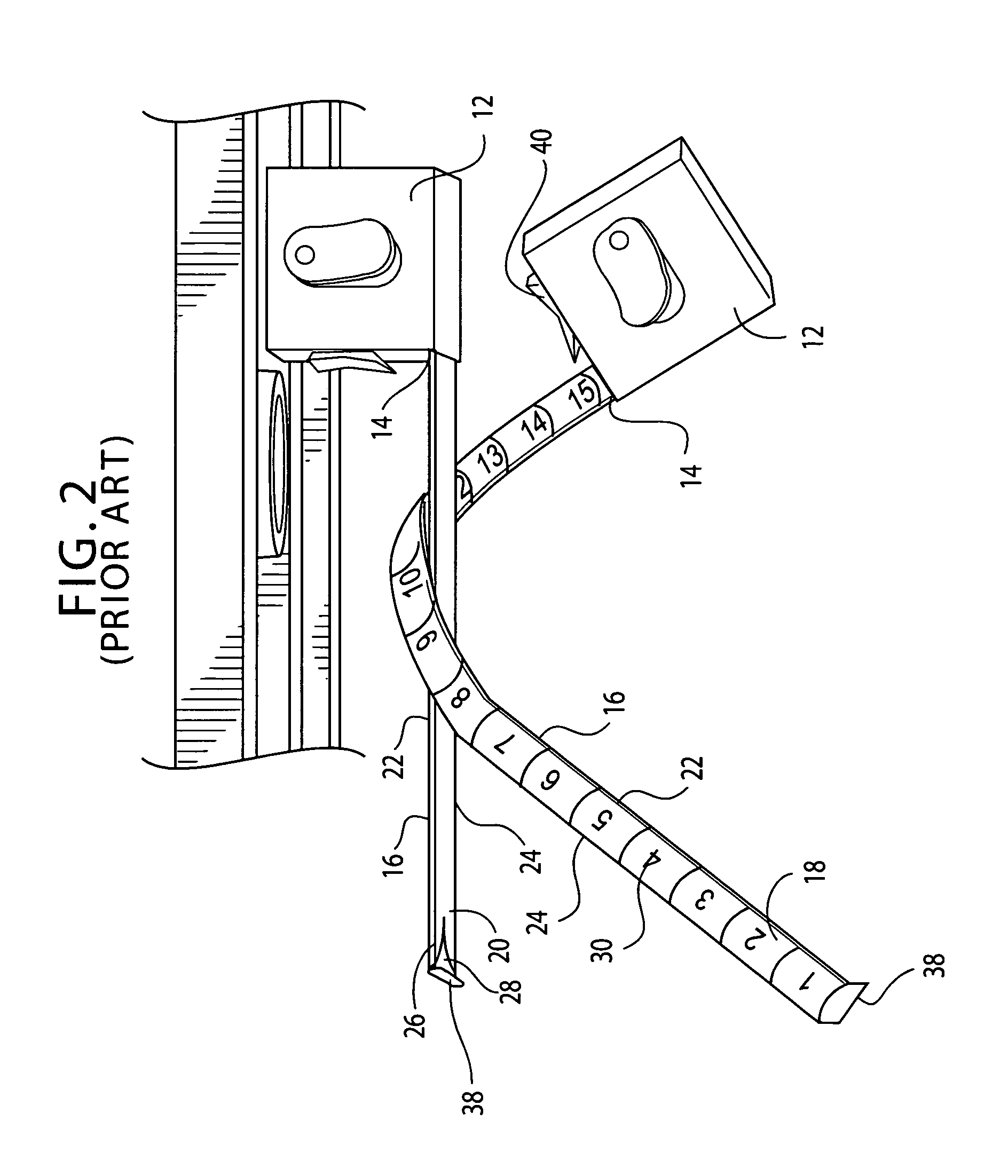
All of the above referenced tapes also share some other, not so widely recognized, features which serve to significantly limit their usefulness.
Thus, despite their popularity, such standard tape measures are not always easy to use.
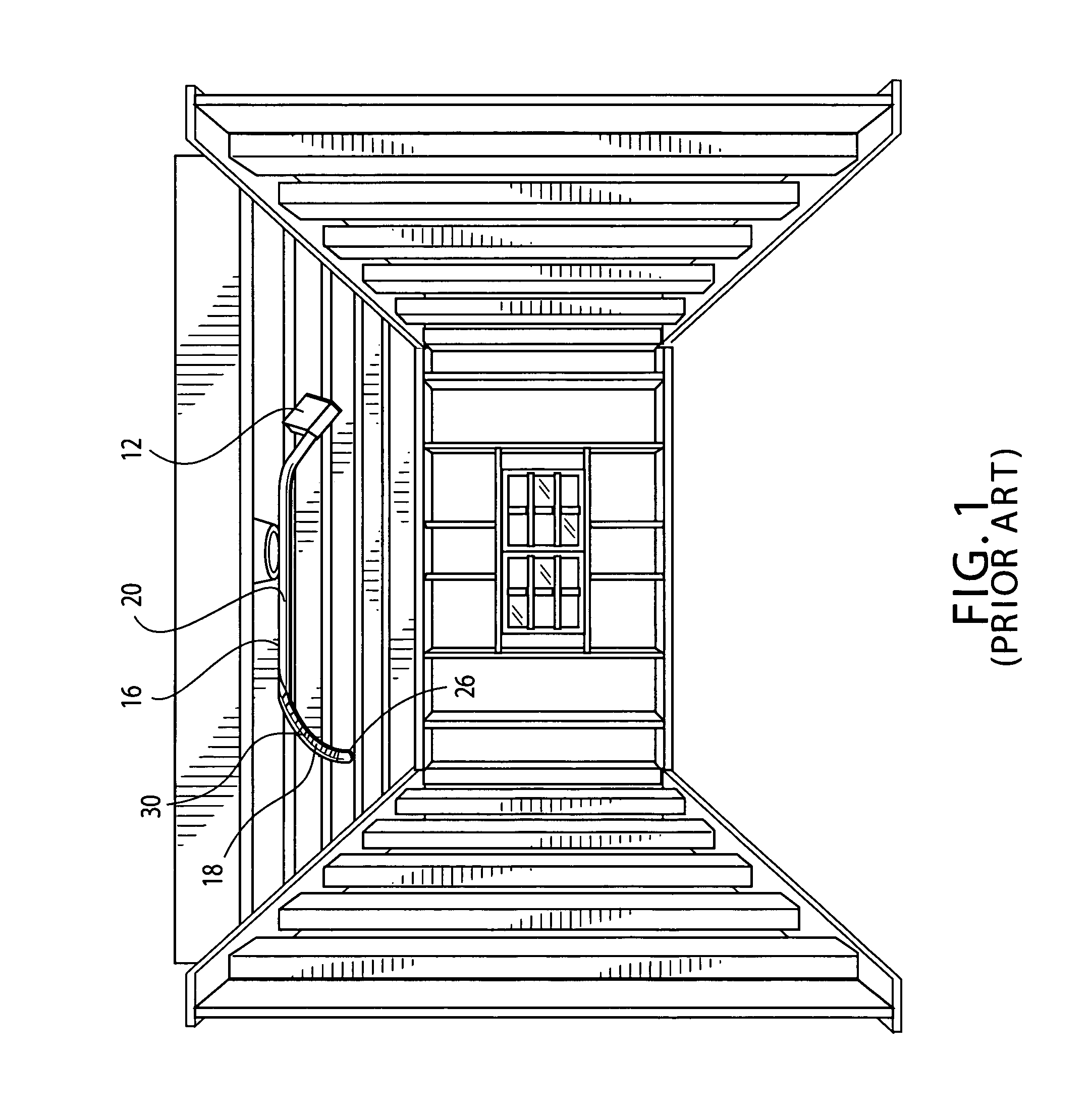
For example, electricians and others often encounter significant problems in using a standard tape measure when they are making measurements from a wall to a distant spot that is more than an arms length away on an adjoining ceiling.
The first obstacle encountered is the lack of any markings on the tape's bottom side.
Meanwhile, the numbers on the tape's top side cannot be seen by its user while he / she is holding the tape up against the ceiling.
Unfortunately, as noted above, the tape cannot be turned over or the top portion of the tape's housing moved away from the ceiling without losing the stiffening effect of the tape's turned-up edges.
Thus, despite this prior art, one finds that standard, tape measures are not very user friendly.

Method used


Image

  • Tape measure
  • Tape measure
  • Tape measure

Examples


Embodiment Construction

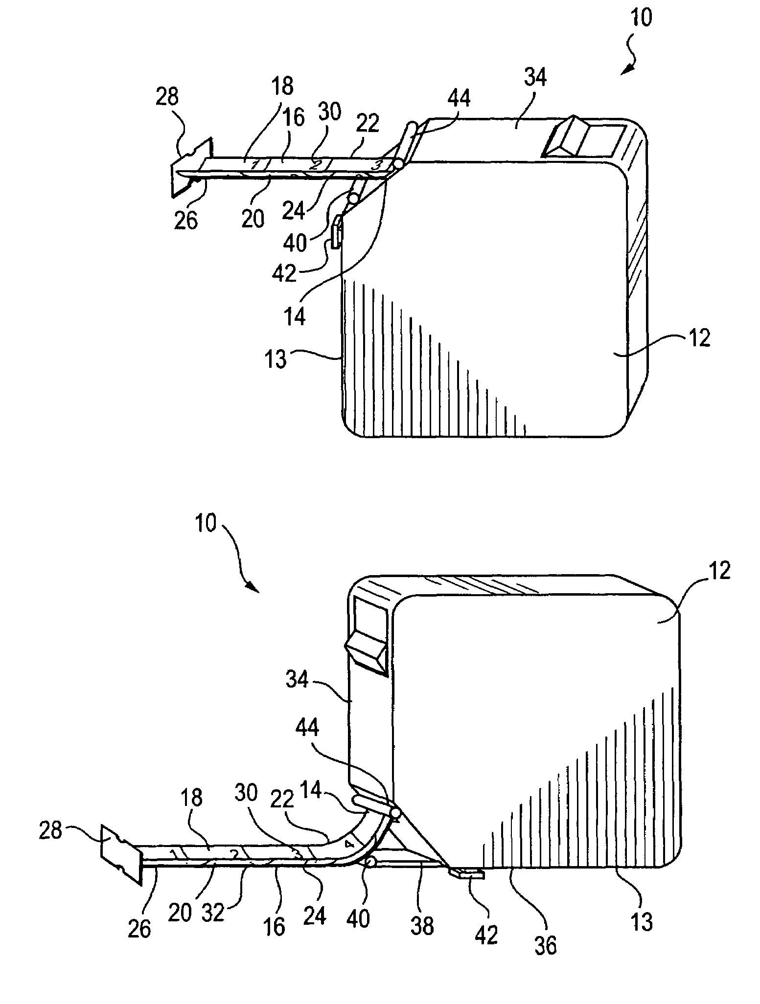
[0028]Referring now to the drawings wherein are shown preferred embodiments and wherein like reference numerals designate like elements throughout, there is shown in FIGS. 3A and 3B a perspective view of an improved retractable, tape measure 10 that has two distinct modes of operation as illustrated in the respective FIGS. 3A and 3B.

[0029]This embodiment includes an approximately rectangular housing 12 having an opening 14, a retractable measuring tape 16 with top 18 and bottom 20 surfaces, edges 22, 24 that turn upward so as to stiffen the tape 16 from being bent downward by the force of gravity, and a free end 26 that extends through the opening 14.

[0030]This embodiment further includes an end stop 28 that is mounted on the tape's free end 26, and top measurement indicia 30 that are inscribed on the top surface 18 of the measuring tape 16. This end stop is notable for having an upper finger that extends above the tape's top surface and a lower finger that extends below the tape's ...


PUM


Abstract

An improved retractable tape measure has, according to a preferred embodiment of the present invention, the features of a standard measure, including a housing with front and rear sides, a boundary edge and a tape opening, a retractable measuring tape positioned within this housing, with the tape having a free end that extends through the housing's opening, plus the improvements yielded by: (a) configuring the housing sides to be tear-drop shaped with a tip end, and (b) locating the tape opening in a portion of the boundary edge proximate the tape's tip end.

Description

CROSS-REFERENCE TO RELATED APPLICATIONS[0001]This application claims the benefit of U.S. Provisional Patent Application No. 60 / 478,243, filed Jun. 16, 2003.BACKGROUND OF THE INVENTION[0002]1. Field of the Invention[0003]The present invention generally relates to geometrical instruments for measuring distance. More particularly, this invention relates to an improved retractable, tape measure.[0004]2. Description of the Related Art[0005]Retractable tape measures have been popular for many years and have often been the subject of patent grants. For example, see U.S. Pat. Nos. 3,908,277, 4,153,996, 4,194,703, 4,439,927, 4,748,746, 4,938,430, 5,210,956 and 5,983,514.[0006]In general, a retractable tape measure includes some widely recognized features, including: a metal tape that is retractably mounted within a housing, a retraction means for retracting the tape through a housing opening, an end stop for preventing the free end of the tape from retracting into the housing, and a lock whi...

Claims


Application Information

Patent Timeline
IPC IPC(8): G01B3/10
CPCG01B3/1041G01B2003/1053
Inventor ODACHOWSKI, MARK
Owner ODACHOWSKI MARK
Learn More