
Notched transmission target for a multiple focal spot X-ray source

a multi-focal spot, x-ray source technology, applied in the direction of x-ray tubes, x-ray tube details, nuclear engineering, etc., can solve the problems of large percentage of electron energy dissipation as heat, many existing target assemblies may not generate enough x-rays,

Inactive Publication Date: 2005-12-13
GE MEDICAL SYST GLOBAL TECH CO LLC
View PDF8 Cites 77 Cited by
  • Summary
  • Abstract
  • Description
  • Claims
  • Application Information

AI Technical Summary

Benefits of technology

"The patent describes a flat panel x-ray tube assembly that includes a cathode assembly with multiple emitter elements and an anode substrate with target wells that face the emitter elements. The target wells have angled sides where first target elements are applied to generate x-rays in response to electrons from the emitter elements. The technical effect of this design is a more efficient and precise generation of x-rays for use in various applications such as medical imaging."

Problems solved by technology

Unfortunately, in many target assemblies utilized in CT systems a large percentage of the electron energy is dissipated as heat.
This generates a multitude of problems.
Many existing target assemblies may not generate sufficient x-rays without a significant introduction of electron energy.
Increase in electron energy in these designs, however, further increases the energy that must be dissipated as heat.
This, in turn, creates a danger to the target surface and is known to melt the target surface if not carefully controlled.
Heat dissipation in combination with adequate x-ray production can also place difficulties on the reduction of x-ray focal spot dimensions.
Existing multiple focal spot designs, however, often suffer from the aforementioned concerns regarding the difficulty of generating sufficient x-rays in order to generate good CT images without melting the target assembly.

Method used


Image

  • Notched transmission target for a multiple focal spot X-ray source
  • Notched transmission target for a multiple focal spot X-ray source
  • Notched transmission target for a multiple focal spot X-ray source

Examples


Embodiment Construction

)

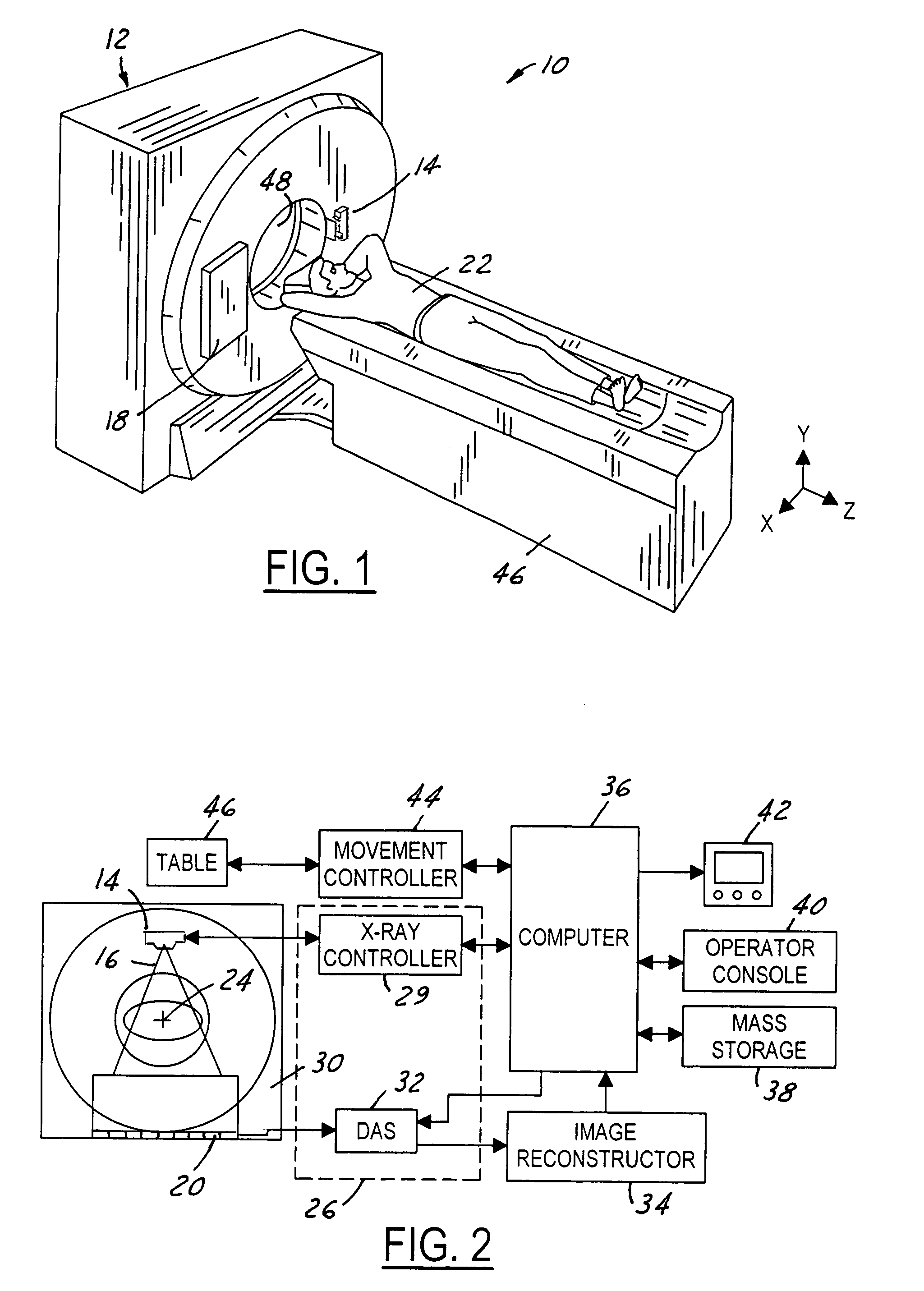
[0015]Referring now to FIG. 1, which is an illustration of a computed tomography (CT) imaging system 10 for use with the flat panel x-ray tube assembly 14 of the present invention. Although a particular CT imaging system 10 has been illustrated, it should be understood that the flat panel x-ray tube assembly 14 of the present invention can be utilized in a wide variety of imaging systems. The CT imaging system 10 includes a scanner assembly 12 illustrated as a gantry assembly. The scanner assembly 12 includes the flat panel x-ray tube assembly 14 for projecting a beam of x-rays 16 toward a detector assembly 18 positioned opposite the flat panel x-ray tube assembly 14. The detector assembly 18 includes a plurality of detector elements 20 which combine to sense the projected x-rays 16 that pass through an object, such as a medical patient 22. Each of the plurality of detector elements 20 produces an electrical signal that represents the intensity of an impinging x-ray beam and hence ...


PUM


Abstract

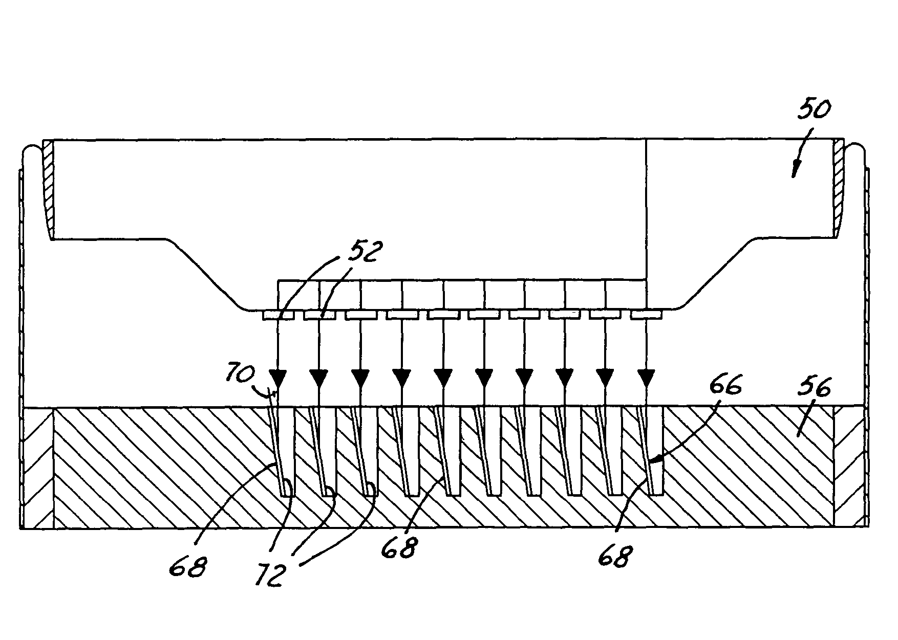
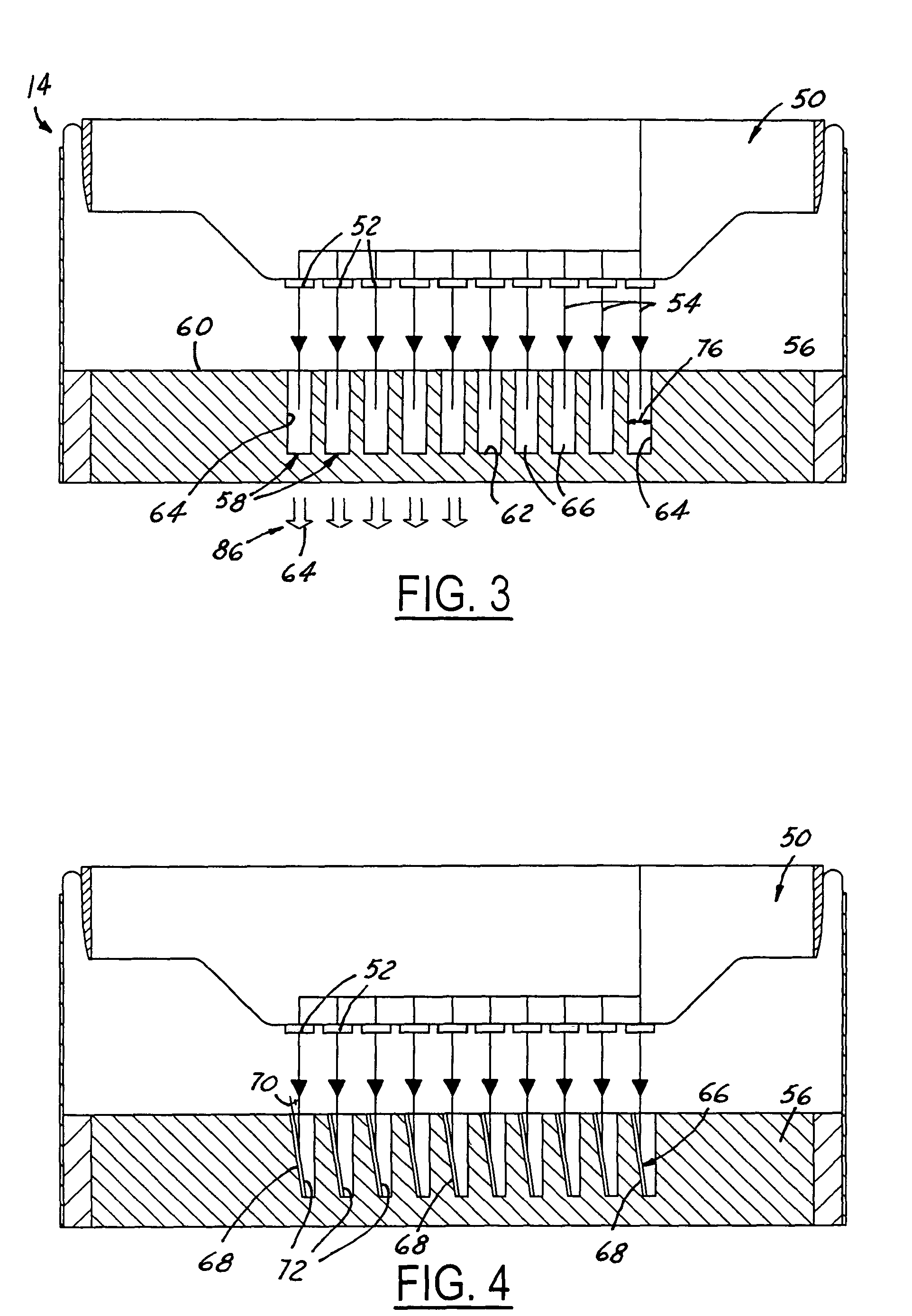
A flat panel x-ray tube assembly is provided comprising a cathode assembly including a plurality of emitter elements. An anode substrate is included having a substrate upper surface facing the plurality of emitter elements and a substrate lower surface. The substrate upper surface is positioned parallel to the plurality of emitter elements. A plurality of target wells are formed in the substrate upper surface. Each of the plurality of target wells comprises a first angled side surface positioned at an acute angle relative to the substrate upper surface. A plurality of first target elements is applied to each to one of the first angled side surfaces. The first target elements generate x-rays in a direction perpendicular to the plurality of emitter elements in response to electrons received from one of the plurality of emitter elements.

Description

TECHNICAL FIELD[0001]The present invention relates generally to an x-ray target assembly, and more particularly, to an x-ray target assembly incorporating multiple focal spots.BACKGROUND OF THE INVENTION[0002]X-ray production is traditionally accomplished through the process of colliding an electron beam of charged particles with a target assembly. X-rays are produced from the interaction of the electron beam and atoms within the target assembly. This is accomplished through the use of target assemblies with high atomic numbers. The electrons are usually produced by a hot filament and are accelerated to the target by a large potential. When they strike the target, they are deflected by the target atoms and this generates the x-rays. This is the principal mechanism for the production of x-rays for use in computed tomography systems.[0003]Unfortunately, in many target assemblies utilized in CT systems a large percentage of the electron energy is dissipated as heat. This generates a mu...

Claims


Application Information

Patent Timeline
Patent Type & Authority Patents(United States)
IPC IPC(8): H01J35/08H01J35/30
CPCH01J35/30H01J2235/087H01J35/116
Inventor WILSON, COLIN RICHARDVERMILYEA, MARK ERNEST
Owner GE MEDICAL SYST GLOBAL TECH CO LLC
Learn More