Switching device

a technology of switching device and switch, which is applied in the direction of relays, contacts, electromagnetic relay details, etc., can solve the problems of low reliability of switching characteristics and inability to easily break products, and achieve the effect of preventing permanent magnets from aging

Inactive Publication Date: 2005-12-13
ORMON CORP
View PDF3 Cites 25 Cited by
  • Summary
  • Abstract
  • Description
  • Claims
  • Application Information

AI Technical Summary

Benefits of technology

[0010]In view of this problem, the invention has an object to provide a switching device, which can be small-sized by improving a shielding performance and can improve the reliability of switching characteristics.
[0013]Even if the flow direction of the current to be broken in use is reversed, moreover, the whirling direction of the arc current produced changes to clockwise or counterclockwise. Specifically, it is unchanged that the arc current whirls along the pole-faces of the permanent magnets, so that the arc current produced can be reliably broken. Even if the current flow direction periodically changes as in case the AC current is to be switched, moreover, the produced arc current whirls alternately in the opposite directions along the pole-faces of the permanent magnets. As a result, the arc current can be reliably broken no matter whether it might be a DC current or an AC current, so that the reliability of the switching characteristics is improved.
[0015]This embodiment can also be applied to the moving contact member having its two end portions brought into and output the stationary contacts, so that its application is widened.
[0019]According to this embodiment, a time lag is established between a plurality of contact switching actions. By making the material of the moving contact member different, therefore, the contact wear by the making current can be suppressed to elongate the contact lifetime.
[0021]According to this embodiment, the arc current produced is so relatively extended in the opposite direction as to whirl. Therefore, the heat is not applied only to one side of the housing so that it can be dispersed over a wide range thereby to provide a switching device having excellent cooling properties.
[0023]According to this embodiment, the pole-faces of the permanent magnets are protected by the shielding wall thereby to provide an effect that the permanent magnets can be prevented from aging.

Problems solved by technology

As a result, the arc current produced cannot be easily broken in a reliable manner, thus causing a problem that the reliability of the switching characteristics is low.

Method used


Image

  • Switching device
  • Switching device
  • Switching device

Examples


Embodiment Construction

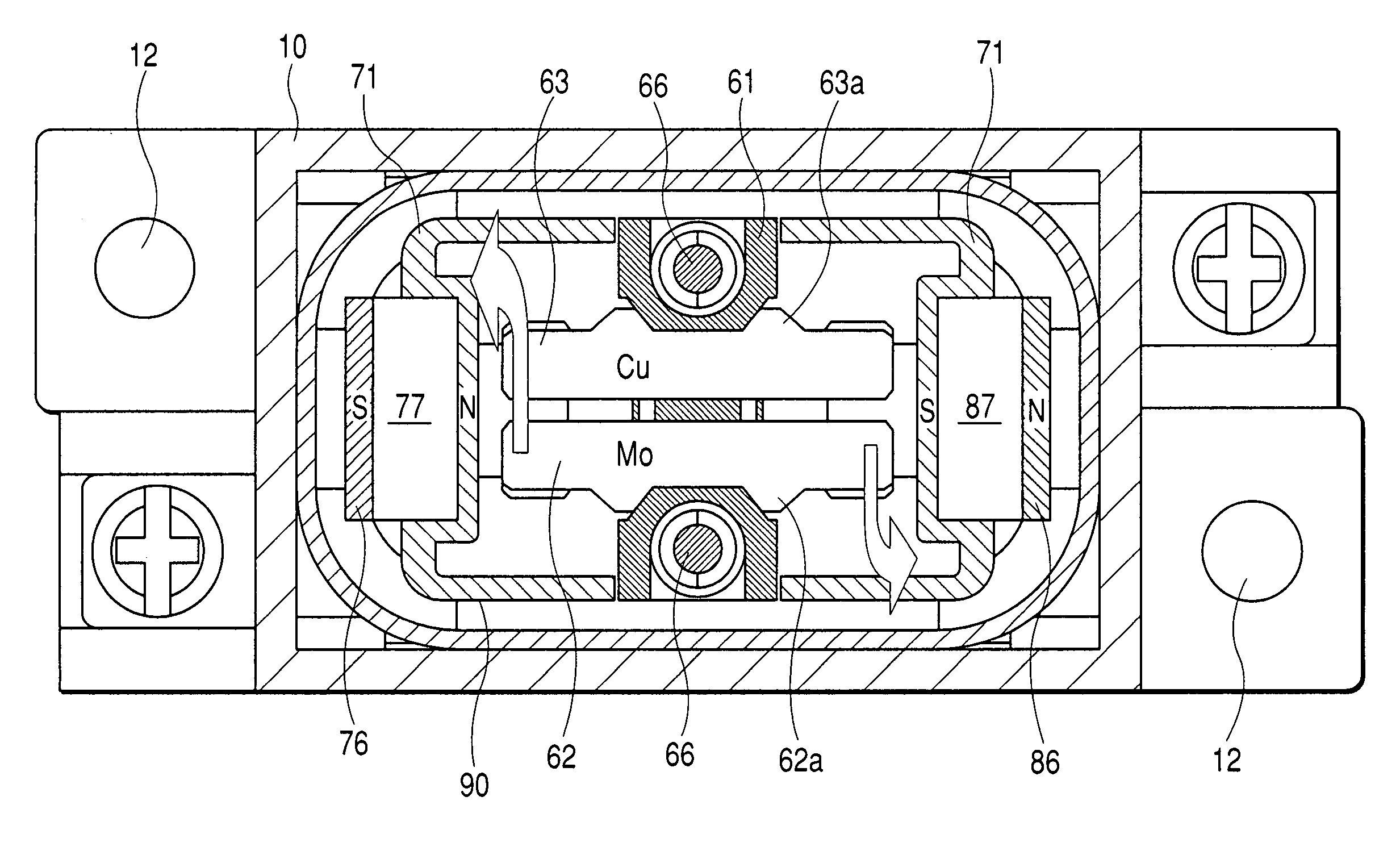
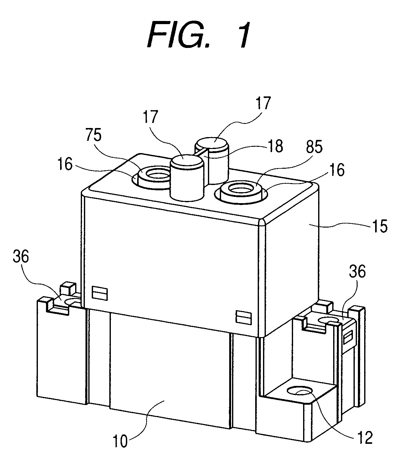
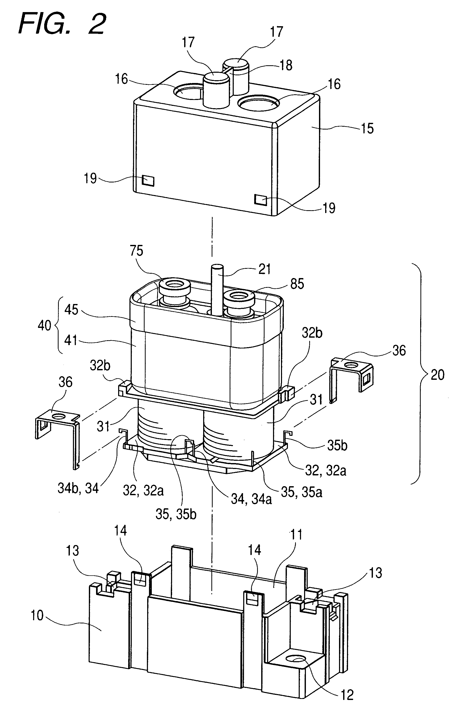
[0039]Embodiment according to the invention will be described with reference to FIG. 1 to FIG. 15. The first embodiment of the invention is applied to a DC load switching relay, in which a relay body 20 is housed in a space defined by a box-shaped case 10 and a box-shaped cover 15 integrated, as shown in FIG. 1 and FIG. 2.

[0040]The box-shaped case 10 is provided, as shown in FIG. 2, with: a recess 11 for housing a later-described electromagnet block 30; fixing through holes 12 in a pair of plane corners positioned on a diagonal line; and connecting recesses 13 positioned in the remaining plane corners. In the connecting recesses 13, connecting nats (not shown in the figure) are embedded.

[0041]The box-shaped cover 15 is so shaped that it can fit the box-shaped case 10 and can house a later-described sealing case block 40. In the ceiling of the box-shaped cover 15, moreover, there are formed connecting holes 16 and 16, from which there are protruded connecting terminals 75 and 85 of t...


PUM


Abstract

A switching device which can be small-sized by improving a shielding performance and can improve the reliability of switching characteristics. A permanent magnet disposed near stationary contacts is arranged in its pole-face perpendicularly of the axis of a moving contact member.

Description

CROSS-REFERENCE TO RELATED APPLICATIONS[0001]This application claims priority from Japanese Patent Application No. 233201 / 2002 filed Aug. 9, 2002.BACKGROUND OF THE INVENTION[0002]1. Field of the Invention[0003]The present invention relates to a switching device and, more particularly, to a switching device such as an electromagnetic relay, a switch or a timer for switching an electric current.[0004]2. Description of the Related Art[0005]As the switching device for closing the DC electric current, there is a closed type relay device, as disclosed in JP-T-9-510040, for example) in the prior art.[0006]As a coil portion 40 is magnetized and demagnetized, more specifically, a plunger 9 is brought into and out of contact with a core center 4 so that an armature assembly 8, as integrated with the plunger 9, and an armature shaft 10 are slit in the axial direction to bring a moving contact disc 21 into and out of contact with stationary contacts 22 and 22.[0007]In the closed type relay devi...

Claims


Application Information

Patent Timeline
Patent Type & Authority Patents(United States)
IPC IPC(8): H01H1/66H01H9/44H01H50/00H01H50/38H01H50/54H01H51/22
CPCH01H1/2025H01H9/443H01H50/546H01H51/2209H01H2009/305H01H2050/025
Inventor NISHIDA, TAKESHIMASUI, YASUYUKIMAENISHI, KOZO
Owner ORMON CORP
Why Eureka
Try Eureka