
Video coding apparatus according to a feature of a video picture

a video and coding technology, applied in the field of video coding apparatus, can solve the problems of inability to enhance coding efficiency, so as to prevent any degradation of coding efficiency

Inactive Publication Date: 2005-12-06
KDD CORP
View PDF9 Cites 56 Cited by
  • Summary
  • Abstract
  • Description
  • Claims
  • Application Information

AI Technical Summary

Benefits of technology

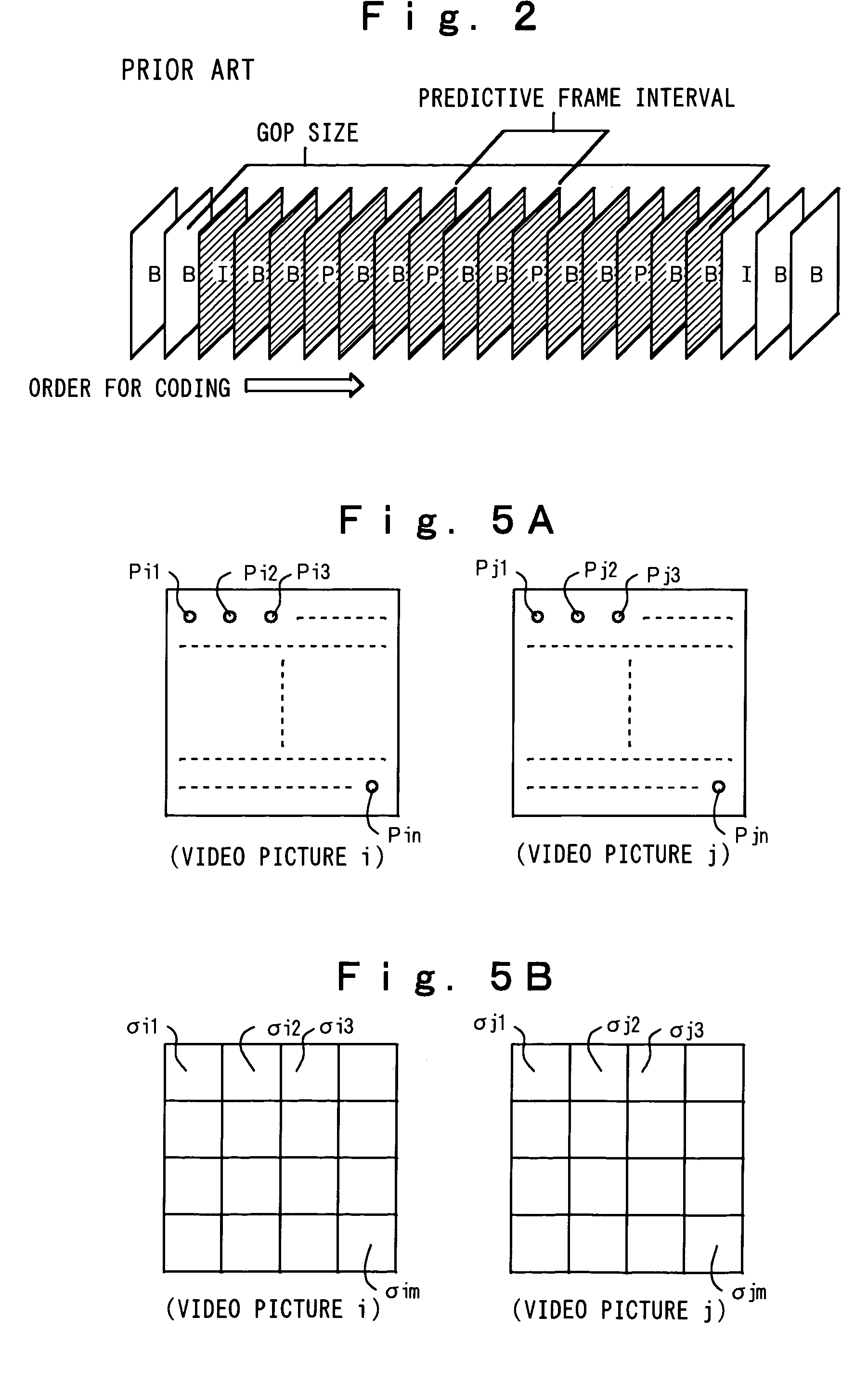
[0016]The present invention has been accomplished in an attempt to solve the above problems experienced by the prior art. Therefore, an object of the present invention is to provide a video coding apparatus in which coding efficiency can be enhanced and a quality of a coded video picture can be stabilized by adaptively changing a GOP size and a predictive frame interval according to the feature of an input video picture or variations of the feature of the input video picture.
[0024]With these features, it is possible to prevent any degradation of the coding efficiency caused by a variation in feature of the input video picture, which was inevitable at the time of fixed selection of the frame / field structures in the prior art. Furthermore, since the discrimination as to whether the input video picture is an interlaced video picture or a non-interlaced video picture, which need be determined before the coding, is automatically detected at the time of the coding, the efficient coding can be carried out irrespective of the feature or structure of the input video picture.

Problems solved by technology

However, since the predictive frame interval is fixed to about 0.1 second irrespectively of the feature of the video picture in the conventional system, the coding efficiency can not be enhanced.
Therefore, even in the case of coding a video picture of a swift motion in which the coding efficiency can be enhanced by adopting the field structure, the coding by the frame structure is continued if the frame structure is previously designated as the coding picture structure, resulting in degradation of the coding efficiency.
To the contrary, in the case where the coding by the field structure is previously designated, the coding efficiency cannot be enhanced since the field structure is fixedly used even if the coding efficiency can be enhanced by the frame structure.

Method used


Image

  • Video coding apparatus according to a feature of a video picture
  • Video coding apparatus according to a feature of a video picture
  • Video coding apparatus according to a feature of a video picture

Examples


fifth embodiment

[0084]Next, a fifth embodiment according to the present invention will be explained in reference to FIG. 11. In the present embodiment, it is discriminated based on each of sequentially input video signals (stationary video signals) whether or not an input video picture is an interlaced video picture. If the input video picture is an interlaced video picture, a downscaled feature plane is created, and then, coding in a frame / field structure is decided based on the result of simple motion estimation processing by the use of the downscaled feature plane.

[0085]In FIG. 11, an interlaced / non-interlaced video discriminant section 51 discriminates whether each of sequentially input video signals 1 is an interlaced video signal or a non-interlaced video signal. The discrimination result is output as interlaced / non-interlaced discriminant information 52 to a downscaled feature plane creation section 53. The downscaled feature plane creation section 53 creates downscaled feature plane informa...

seventh embodiment

[0099]FIG. 17 is a block diagram illustrating the configuration of a seventh embodiment according to the present invention. The same reference numerals as those in FIG. 11 designate like or corresponding constituent elements. In the present embodiment, a video coding apparatus comprises an interlaced / non-interlaced video discriminant section 51 and a frame / field structure decision section 57. The interlaced / non-interlaced video discriminant section 51 discriminates whether or not an input video picture is an interlaced video picture. The present embodiment is characterized in that the frame / field structure decision section 57 selects coding by a field structure in the case where the input video picture is an interlaced video picture; to the contrary, it selects coding by a frame structure in the case where the input video picture is a non-interlaced video picture.

[0100]FIG. 18 is a block diagram illustrating the configuration of an eighth embodiment according to the present inventio...


PUM


Abstract

A variance between sequential video pictures is extracted, and then, a GOP boundary position is decided based on inter-frame variance information. Furthermore, simple motion estimation is carried out with respect to video pictures inside one GOP. If a motion variation between the video pictures is large, a small predictive frame interval is taken; to the contrary, if the motion variation is small, a large predictive frame interval is taken. The simple motion estimation is carried out between two downscaled feature planes at a timewise fixed interval with respect to a video picture which is discriminated to be an interlaced video picture, wherein a motion compensatory prediction error at that time is output as image variance information. If the image variance is small, coding is conducted by a frame structure; to the contrary, if the image variance is large, the coding is conducted by a field structure. With the above-described processing, it is possible to provide a video coding apparatus for deciding a GOP size and the predictive frame interval according to the feature of the input video picture, and another video coding apparatus for adaptively switching the coding by the frame / field structures according to the feature of the input video picture.

Description

BACKGROUND OF THE INVENTION[0001]1. Field of the Invention[0002]The present invention relates to a video coding apparatus and, more particularly, to a video coding apparatus for performing coding by using motion compensatory prediction of a digital video signal.[0003]2. Description of the Related Art[0004]Among highly efficient coding systems for coding sequentially input video signals in a fewer code quantity, coding systems by the use of the motion and correlation between video pictures of video signals include motion compensatory prediction coding which decodes to reproduce a video picture coded in the past and uses motion information per small block derived from the video picture. One example of the conventional motion compensatory prediction coding is illustrated in FIG. 1.[0005]In FIG. 1, when an input video signal 1 of a first screen is input, each of switches is controlled to be connected onto a side (1) by a coding mode control section 12, and the input video signal 1 is in...

Claims


Application Information

Patent Timeline
IPC IPC(8): G06T9/00H04B1/66H04N7/12H04N7/26H04N7/46H04N7/50
CPCH04N19/139H04N19/172H04N19/115H04N19/61H04N19/112H04N19/114H04N19/137H04N19/177H04N19/59
Inventor YONEYAMA, AKIONAKAJIMA, YASUYUKIYANAGIHARA, HIROMASASUGANO, MASARU
Owner KDD CORP
Learn More