
Skin-marking device

a skin-marking device and skin-marking technology, applied in the field of medical and surgical tools, can solve the problems of not including the measuring indicia of the device for accurately measuring the skin of the patient, and none of the prior art skin-marking devices are of a shape that prevents them from rolling off the flat surface, and achieves the effect of minimal packaging

Inactive Publication Date: 2005-12-06
GRIFFIN MICHAEL
View PDF13 Cites 53 Cited by
  • Summary
  • Abstract
  • Description
  • Claims
  • Application Information

AI Technical Summary

Benefits of technology

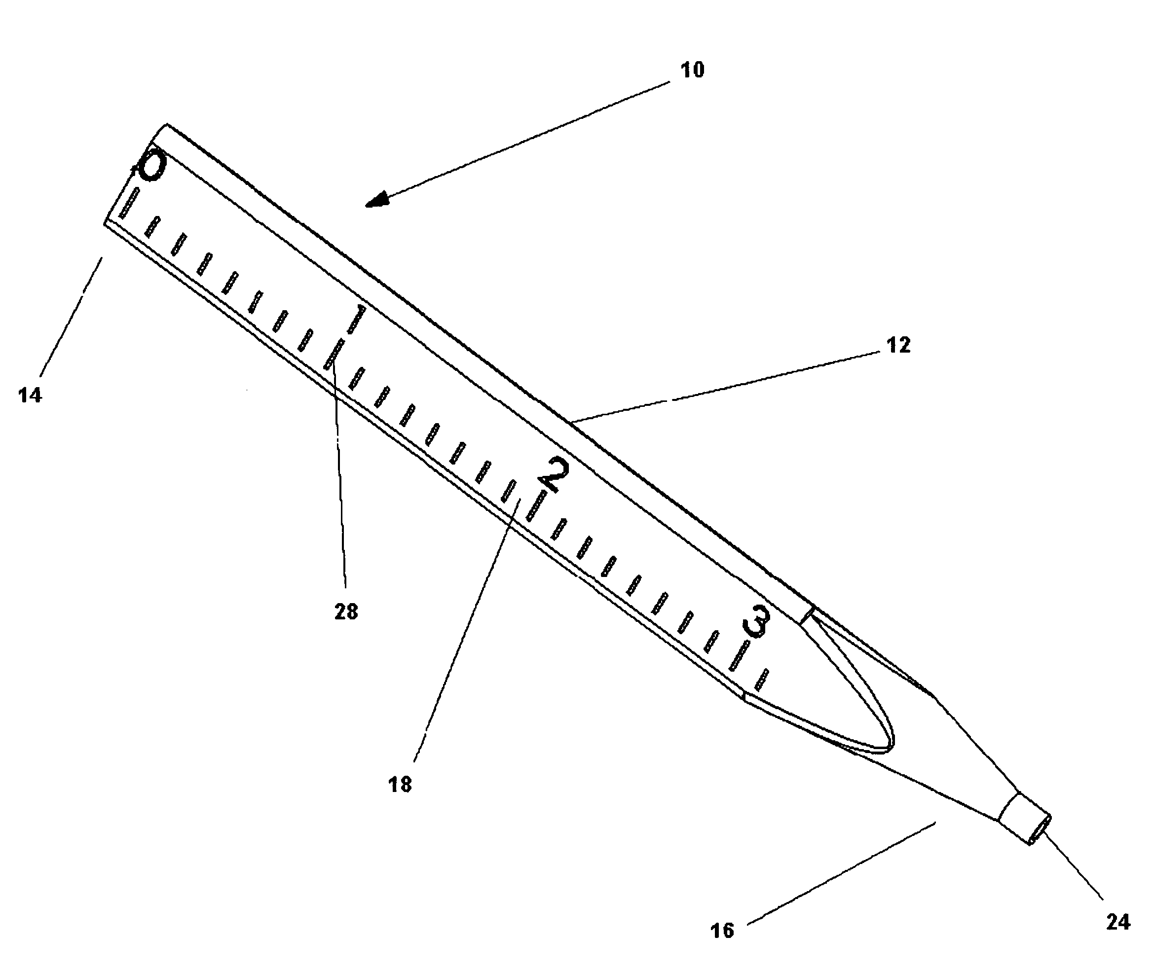
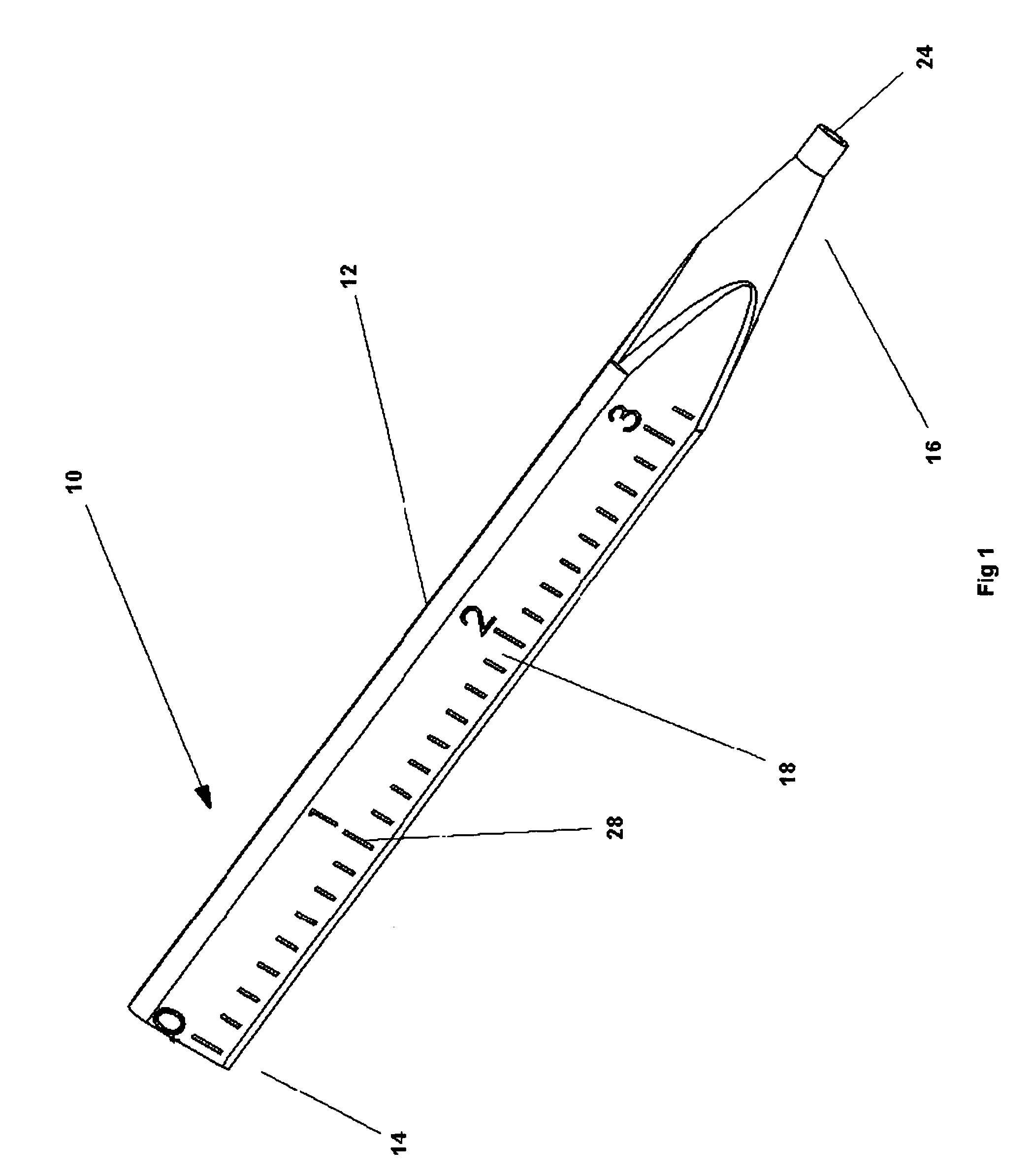
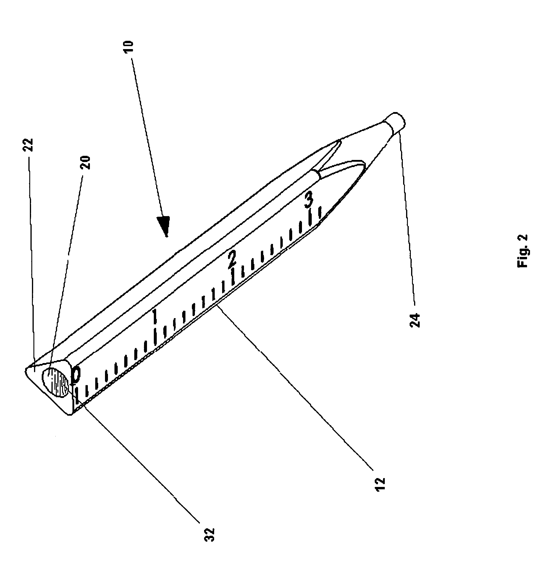
[0005]Having recognized these conditions, the present invention is directed to a skin-marking device having a holder body comprised of sidewalls. The sidewalls define a shape of the holder body other than round, preferably triangular, to prevent the skin marker from accidentally rolling off a flat surface. One or more of the sidewalls may have measuring indicia disposed thereon, enabling the device to act as a ruler for accurately measuring distances. More preferably, a cap adapted to fit over a portion of the holder body has measuring indicia disposed thereon. In this manner, a surgeon may accurately measure distances with the cap and then conveniently and efficiently mark those distances.
[0007]The holder body may optionally include a pocket clip or magnet attached thereto. In the alternative, a pocket clip or magnet may be disposed on the cap, depending on the cap's length. In this manner, the skin marker can be advantageously clipped inside a person's pocket or prevented from sliding off a magnetic drape or other magnetic surface, respectively.

Problems solved by technology

While the above-mentioned devices represent an improvement in the skin-marking field, none of these prior art skin-marking devices are of a shape that precludes them from rolling off flat surfaces.
Moreover, these devices do not incorporate measuring indicia for accurately measuring a patient's skin to determine and mark the length of an incision or the like.

Method used


Image

  • Skin-marking device
  • Skin-marking device
  • Skin-marking device

Examples


Embodiment Construction

[0016]Preferred embodiments will now be described with reference to the drawings. For clarity of description, any element numeral in one figure will represent the same element if used in any other figure.

[0017]FIG. 1 illustrates a skin-marking device 10 having a top end 14 and a bottom end 16. The device 10 comprises a holder body 12. The holder body 12 is defined by sidewalls 18. The sidewalls18 define a channel or reservoir 20 located in the central portion of the skin marker 10, as shown in FIG. 2.

[0018]At the top end 14 of the device 10, a cap 26 may be disposed for helping contain fluid 32 or the like held within the reservoir 20, as illustrated in FIGS. 1 and 2. Similarly, a nib holder 24 may be disposed at the other end 16 of the device 10 for keeping fluid 32 within the reservoir 20. Detailed views of the cap 26 and nib holder 24 are illustrated in FIGS. 4 and 5, respectively, and are discussed in detail below.

[0019]Should the present invention comprise the nib holder 24 and...


PUM


Abstract

A skin-marking device is disclosed that has a holder body and cap having a shape other than round, preferably triangular, to prevent the device from accidentally rolling off a flat surface. Measuring indicia is disposed on the device for accurately measuring distances. The device contains a dermatologically acceptable coloring agent for marking a patient's skin and one that may be selected from the group consisting of a radioopaque substance for x-ray diagnostic purposes, a fluorescent composition, a non-magnetic hydrogel for nuclear magnetic resonance imaging diagnostic purposes, a sterilizable gel ink, a combination of any of these, and a mixture of any of these. The holder body or cap may include a pocket clip or magnet attached thereto to permit the skin marker to be clipped inside a person's pocket or prevented from sliding off a magnetic drape or other magnetic surface, respectively. The skin marker may also come in a number of different sizes, one of which is optionally short enough to allow it to fit into a needle counter box to be packaged as part of a mini kit.

Description

BACKGROUND OF THE INVENTION[0001]The field of the present invention relates to medical and surgical tools and particularly to skin-marking devices for marking skin to guide a surgeon in making a proper incision, to aid in diagnostics, or other such similar purposes.[0002]Skin-marking devices are commonly used by the medical industry to color a patient's skin prior to surgery to mark the proper place and length of the incision or incisions to be made during the operation. Skin markers are also commonly used to delineate boundary areas requiring medical therapy or monitoring, such as in conjunction with radiation treatment, or for marking the skin for diagnosis by X-ray tomography and nuclear magnetic resonance imaging.[0003]Skin marking devices in the past have included felt tip pens, magic markers, and other commercially available writing instruments. As time progressed and applications varied, such conventional marking devices have been improved upon. Today, their shape and marking...

Claims


Application Information

Patent Timeline
IPC IPC(8): A61B17/00A61B19/00
CPCA61B19/54A61B2017/00876A61B2019/461A61B2019/5408A61B2019/545A61B2090/061A61B90/39A61B2090/3908A61B2090/395
Inventor GRIFFIN, MICHAEL
Owner GRIFFIN MICHAEL
Learn More