
Bulkhead connector for low leak rate disc drives

a technology of disc drives and bulkhead connectors, which is applied in the direction of casings/cabinets/drawers, instruments, casings/cabinets/drawers, etc., can solve the problems of bulkhead connectors still presenting a leakage problem, gaskets not providing hermetic seals with respect to air, and drives that have not been commercially successful

Inactive Publication Date: 2005-11-29
SEAGATE TECH LLC
View PDF14 Cites 71 Cited by
  • Summary
  • Abstract
  • Description
  • Claims
  • Application Information

AI Technical Summary

Problems solved by technology

Despite the advantages of helium filled drives, such drives have not been commercially successful.
This is mainly due to problems associated with the helium (or other low density gas) leaking from the drives over time.
Indeed, such gaskets do not provide hermetic seals with respect to air (i.e., the gaskets are also permeable to the larger atoms of nitrogen and oxygen in air) since it is air that typically displaces the helium gas that leaks from the drive.
However, typical bulkhead connectors still employ a gasket to provide a seal between the bulkhead connector and the base deck.
Therefore, the bulkhead connector still presents a leakage problem.
First, the seals do not outgas and thus do not contribute to the contamination of the interior of the drive.
Secondly, the seals may be reused if necessary during the assembly of the disc drive, such as when an assembled drive fails to pass certification testing and must be “reworked.” Unfortunately, while such gasket seals are convenient, they simply do not provide a sufficient hermetic seal to maintain the required concentration of helium (or other low density gas) within the disc drive over the service life of the drive.
As helium leaks out of a disc drive and is replaced by air, the drive is subjected to undesirable operational effects possibly leading to failure of the drive.
For example, the increased concentration of air may increase the turbulent forces on the drive heads due to the increased drag forces within the drive, and may further cause the heads to fly at too great a distance above the discs, thereby increasing the instances of read / write errors.
The risk of unexpected failure due to inadequate amounts of helium is a considerable drawback to helium filled disc drives, particularly since the data stored within the disc drive can be irretrievably lost if the disc drive fails.

Method used


Image

  • Bulkhead connector for low leak rate disc drives
  • Bulkhead connector for low leak rate disc drives
  • Bulkhead connector for low leak rate disc drives

Examples


Embodiment Construction

[0020]In the following description, for the purposes of explanation, numerous specific details are set forth in order to provide a thorough understanding. It will be apparent, however, to one skilled in the art that embodiments of the present invention may be practiced without some of these specific details. In other instances, well-known structures and devices are shown in block diagram form.

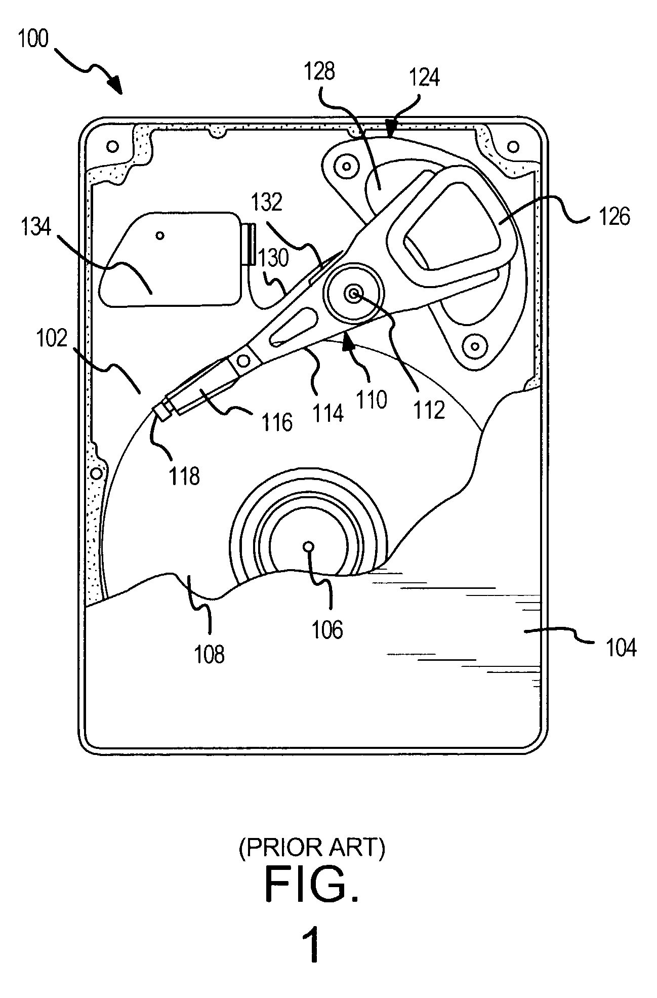
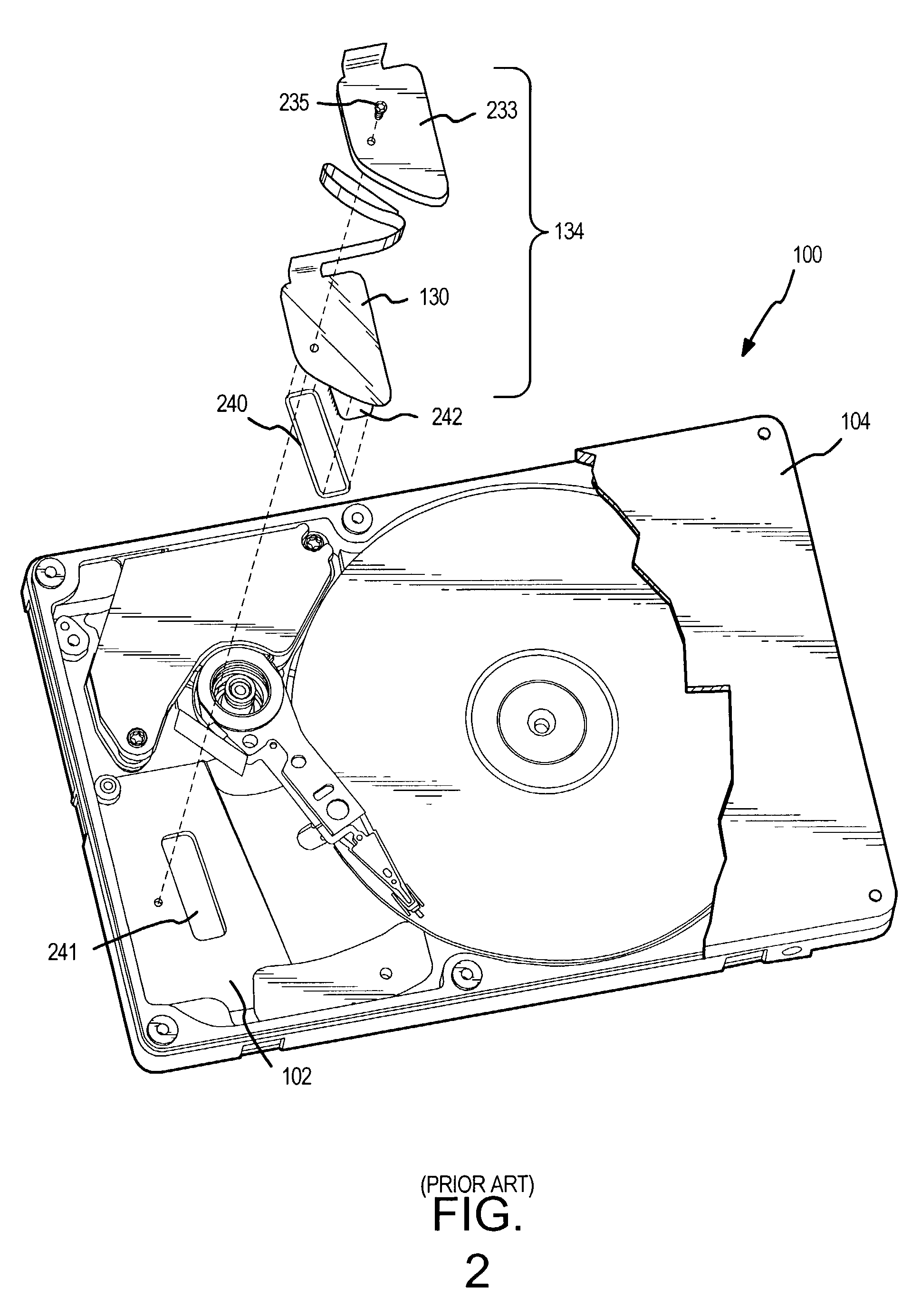
[0021]FIG. 1 is a plan view of a prior art disc drive 100 showing the primary internal components of the disc drive. The disc drive 100 includes a base 102 to which various components of the disc drive 100 are mounted. The drive components include a spindle motor 106, which rotates one or more discs 108 at a constant high speed. Information is written to and read from tracks on the discs 108 through the use of an actuator assembly 110, which rotates during a seek operation about a bearing shaft assembly 112 positioned adjacent the discs 108. The actuator assembly 110 includes a plurality of act...


PUM

PropertyMeasurementUnit
widthaaaaaaaaaa
thicknessaaaaaaaaaa
thicknessaaaaaaaaaa

Abstract

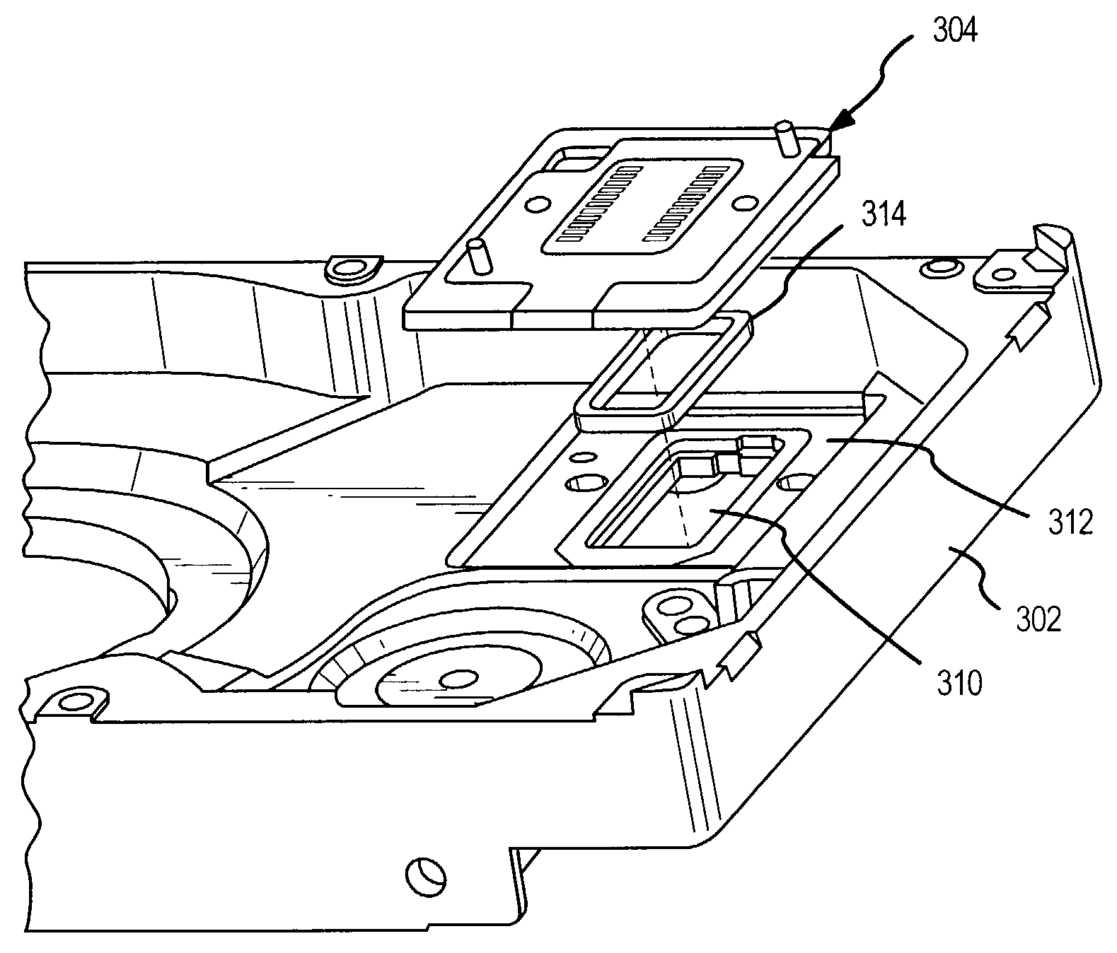
A disc drive has a rotatable disc carried by a spindle motor and an actuator assembly with a read / write head. A base deck supports the spindle motor and the actuator assembly and defines a connector opening for transmitting electrical signals from the read / write head through the base deck to a printed circuit board attached to an exterior surface of the base deck. A bulkhead connector is adhesively affixed to the base deck to cover the connector opening. The bulkhead connector comprises a backing plate and a flex circuit bonded to the backing plate. The flex circuit extends across a top surface of the backing plate, wraps around one edge of the backing plate, and extends across a bottom surface of the backing plate.

Description

FIELD OF THE INVENTION[0001]The invention relates generally to the field of disc drives. More particularly, the invention relates to an improved bulkhead connector for low leak rate disc drives.BACKGROUND OF THE INVENTION[0002]A disc drive typically includes a base deck to which various components of the disc drive are mounted. A top cover cooperates with the base to form a housing that defines an internal, sealed environment for the disc drive. The components include a spindle motor, which rotates one or more discs at a constant high speed. Information is written to and read from tracks on the discs through the use of an actuator assembly. The actuator assembly includes actuator arms, which extend towards the discs, with one or more suspensions or flexures extending from each of the actuator arms. Mounted at the distal end of each of the flexures is a read / write head, which includes an air bearing slider enabling the head to fly in close proximity above the corresponding surface of...

Claims


Application Information

Patent Timeline
Patent Type & Authority Patents(United States)
IPC IPC(8): G11B25/04G11B33/12
CPCG11B25/043G11B33/122
Inventor BERNETT, FRANK W.
Owner SEAGATE TECH LLC
Learn More