
Half-rate linear quardrature phase detector for clock recovery

a phase detector and clock recovery technology, applied in pulse manipulation, pulse technique, instruments, etc., can solve the problems of “no reason why consecutive data pulses need to be separated by zero-amplitude intervals, eye centering, and difficult or unreliable, so as to minimize control signal ripple and minimize jitter

Inactive Publication Date: 2005-11-29
ALTERA CORP
View PDF22 Cites 17 Cited by
  • Summary
  • Abstract
  • Description
  • Claims
  • Application Information

AI Technical Summary

Benefits of technology

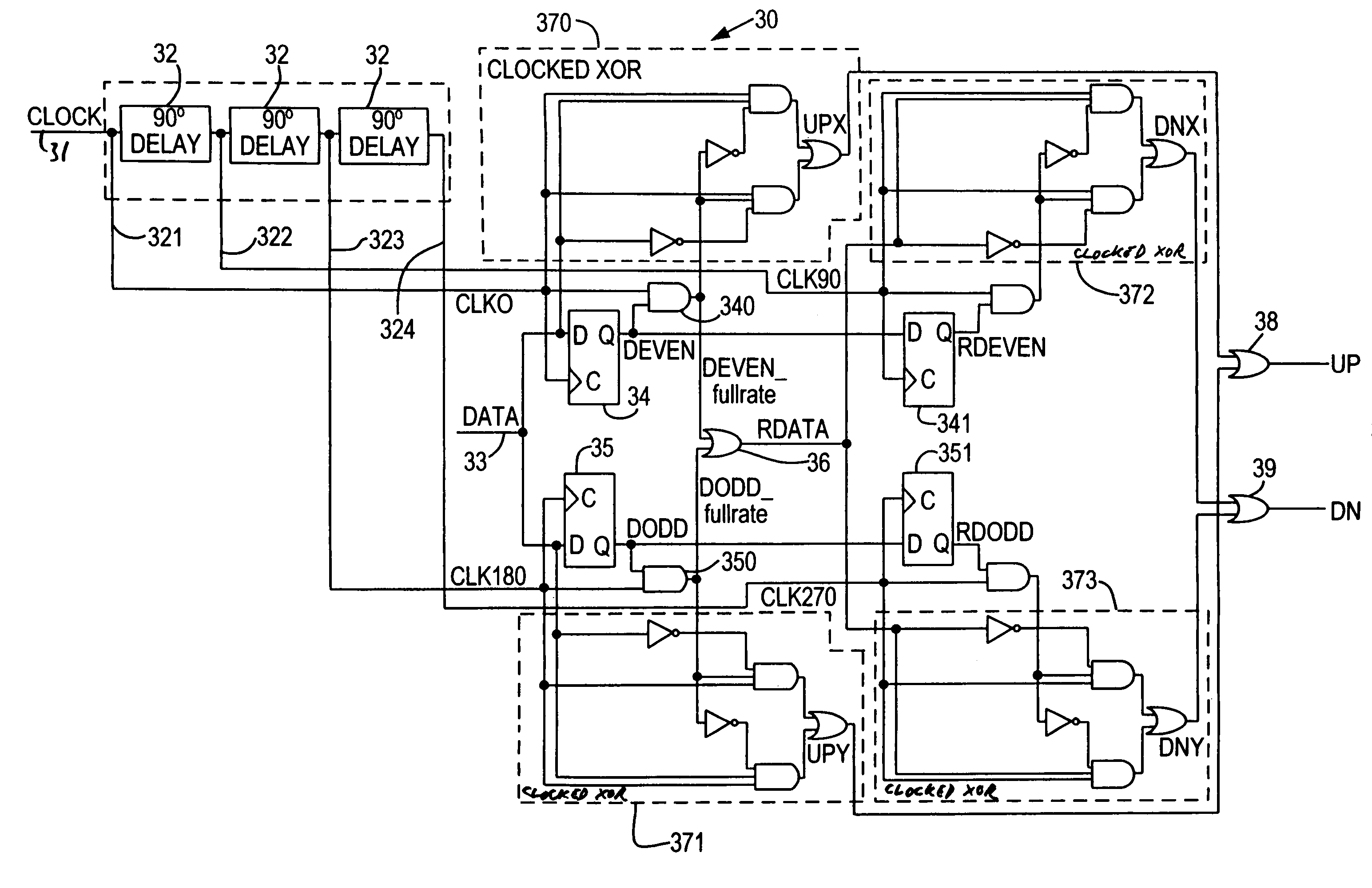
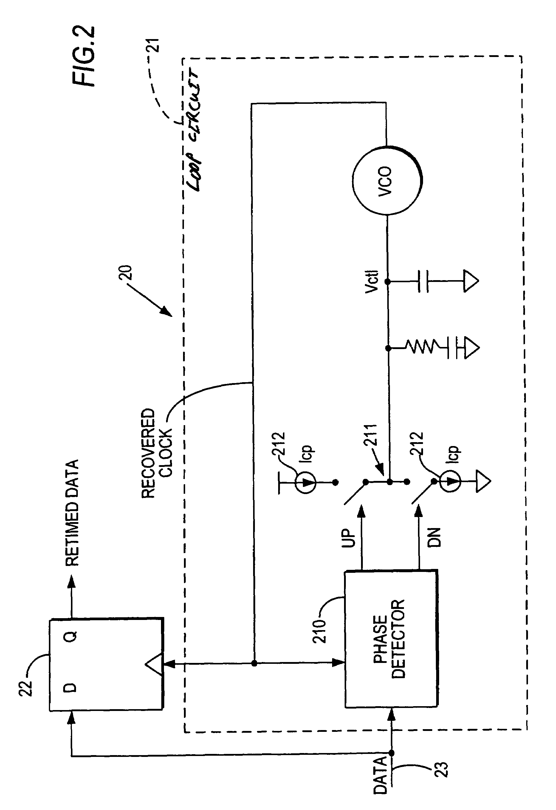
[0008]The present invention minimizes jitter in a recovered clock application by providing a phase detector, for use in a clock recovery circuit, that is linear—and therefore predictable, that operates at half the clock rate—and whose performance therefore does not degrade as quickly at high speeds, and that produces UP and DOWN control pulses of equal width—thereby minimizing control signal ripple. This is achieved by using a quadrature clock to retime the data, and deriving different portions of the UP and DOWN control pulses from different quadrature phases of the retimed data.

Problems solved by technology

However, there is no reason why consecutive data pulses need be separated by zero-amplitude intervals.
However, when the clock must be recovered from the data, clock recovery errors could make centering the sampling time in the data eye—“eye centering”—difficult or unreliable.
Any such problems are compounded in a programmable logic device, where the circuit paths, as well as the clock recovery circuitry, differ from one user logic design to the next.
Variation or ripple in the control signal may cause unacceptable jitter in the oscillator output, giving rise to clock recovery errors, thereby causing eye centering errors which in turn result in data read errors.
For example, a full-rate linear phase detector, such as a Hogge phase detector, operates predictably but its performance degrades as the clock rate increases.
A nonlinear phase detector such as a Bang Bang phase detector causes a large ripple on the control signal making the loop circuit output unpredictable.
A half-rate linear phase detector is linear, therefore predictable, but produces a DOWN (or REFERENCE) signal having twice the pulse width of the UP (or ERROR) signal, resulting in a large ripple effect on the oscillator control signal.

Method used


Image

  • Half-rate linear quardrature phase detector for clock recovery
  • Half-rate linear quardrature phase detector for clock recovery
  • Half-rate linear quardrature phase detector for clock recovery

Examples


Embodiment Construction

[0017]As described above, the present invention provides a reliable linear phase detector that operates at half the data rate but still provides UP and DOWN control pulses of substantially equal width, by using a half-rate quadrature clock. Specifically, even though the recovered clock operates at half the data rate, because a quadrature clock is derived from the recovered clock, different phases of the clock can operate on different transitions in the data. Thus, while a half-rate clock would ordinarily miss every other transition in the full-rate data signal, the different phases of the quadrature clock are able to monitor, in the aggregate, all transitions. Each phase of the quadrature clock results in a partial UP or DOWN control signal representing those transitions monitored by that phase, but the partial signals can be combined into a single UP or DOWN control signal.

[0018]The invention will now be described with reference to FIGS. 1–4.

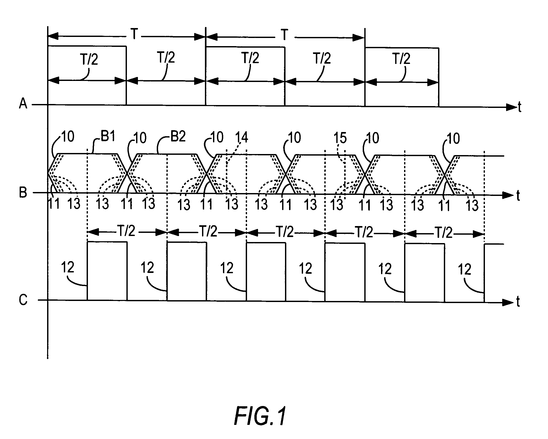
[0019]FIG. 1 shows as waveform A a clock...


PUM


Abstract

A half-rate linear phase detector is particularly well-suited to clock data recovery in a serial data interface. The phase detector uses a quadrature clock to process different portions of the incoming data with different phases of the clock. The resulting component signals can be combined to provide the expected UP and DOWN phase detector output control signals. The phase detector output signals are balanced and of uniform width, minimizing oscillator control signal ripple in the clock data recovery circuit, while the linearity of the phase detector makes its output predictable.

Description

BACKGROUND OF THE INVENTION[0001]This invention relates to phase detection in clock data recovery applications. More particularly, this invention relates to a phase detector, for use in clock data recovery, that is predictable and stable.[0002]It is almost axiomatic that digital systems are clocked. For a clock of period T, the clock signal is typically a series of square (or rectangular) pulses of durations T / 2, separated by zero-amplitude intervals of durations T / 2. Such a clock has a rate or frequency of 1 / T. The clock is used to time data signals, with each data pulse having a duration T / 2. However, there is no reason why consecutive data pulses need be separated by zero-amplitude intervals. Therefore, two or more (n) consecutive data pulses can be transmitted as a single continuous “high” signal of duration nT. In each clock period T, one data pulse can be transmitted. Thus, the data rate of the system is the same as that of the clock rate. In a double data rate system, data is...

Claims


Application Information

Patent Timeline
IPC IPC(8): G01R25/00H03D13/00
CPCH03D13/004
Inventor MEI, HAITAOWANG, SHOUJUNBAIG, MASHKOORBEREZA, BILLKWASNIEWSKI, TAD
Owner ALTERA CORP
Learn More