
Acoustic fluid-gauging system

a fluid gauge and fluid gauge technology, applied in the direction of liquid/fluent solid measurement, volume measurement, volume measurement, etc., can solve the problems of noise signal and difficult to distinguish between the signal produced by the true reflection of the fuel surface, and the problem of making the problem wors

Inactive Publication Date: 2005-11-29
ONTIC ENG & MFG UK
View PDF15 Cites 12 Cited by
  • Summary
  • Abstract
  • Description
  • Claims
  • Application Information

AI Technical Summary

Problems solved by technology

There are various problems with ultrasonic gauging systems.
In particular, it can be difficult to distinguish between the signal produced by the true reflection off the fuel surface and noise signals, such as reflections from the surface of the probe.
This problem can be made worse if the fuel surface is at an angle, if it is disturbed by waves or foam, is rapidly moving or is otherwise perturbed.

Method used


Image

  • Acoustic fluid-gauging system
  • Acoustic fluid-gauging system

Examples


Embodiment Construction

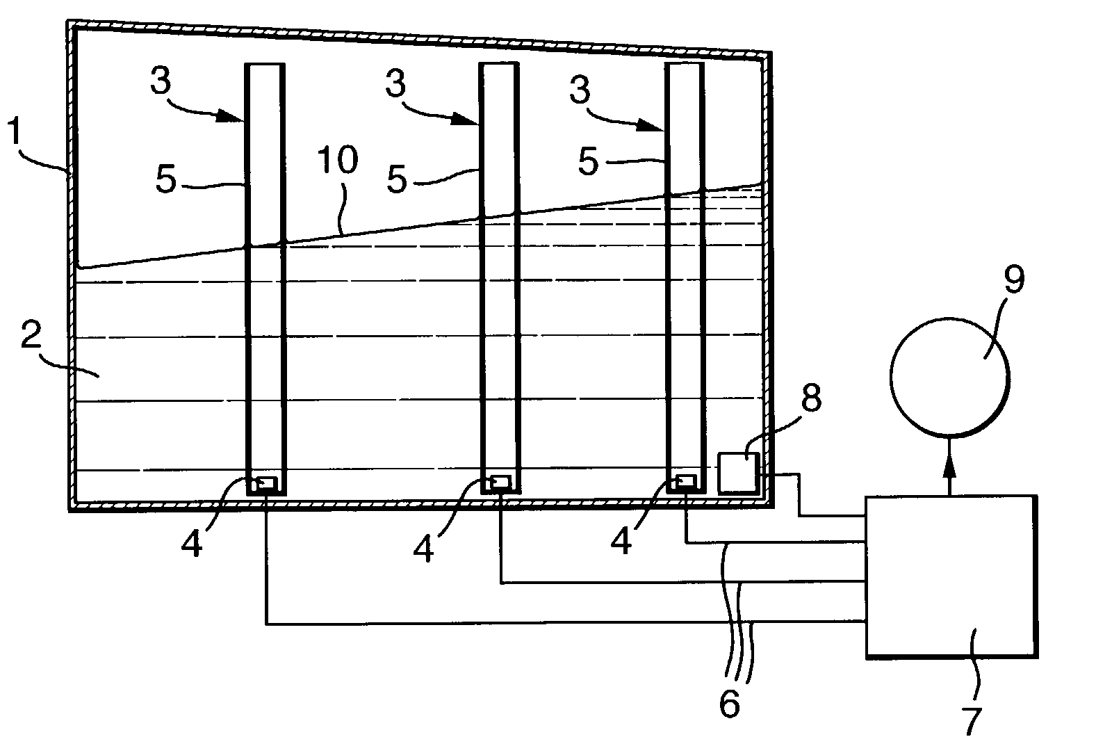
[0014]With reference first to FIG. 1, the system comprises a fuel tank 1 containing liquid fuel 2 and three ultrasonic gauging probes 3 mounted substantially vertically in the tank. It will be appreciated that different numbers of probes could be used.

[0015]The probes 3 may be of a conventional kind, including a piezoelectric ultrasonic transducer 4 that functions both to transmit and receive ultrasonic energy. The transducer 4 is mounted at the bottom of a cylindrical tube or stillwell 5, which is open at the bottom and top to allow fuel to flow into and out of the stillwell so that it takes up the same height as outside the probe. The transducer 4 of each probe 3 is electrically connected by a wire 6 to a processing unit 7 operating to supply signals both to and from the probes. In particular, the processing unit 7 supplies voltage pulses to the transducers 4 to cause them to propagate bursts of ultrasonic energy. The processing unit 7 receives voltage signals from the transducers...


PUM


Abstract

An aircraft ultrasonic fuel-gauging system has a processing unit that energizes probes and receives signals from transducers arising from energy reflected back from the fuel surface. In addition to determining the time between transmission of a signal from the transducer and reception of its reflection from the fuel surface, the processing unit also determines the time of reception of subsequent reflections caused by reflection back from the lower end of the probe. The processing unit determines whether the subsequent reflected signals are within predetermined limits of the time interval between transmission and reception of the first reflected signal in order to confirm the validity of the first signal. The processing unit also counts the number of subsequent reflected signals received within predetermined time intervals to assign a confidence level and this used to select between different incompatible signals, such as signals from that probe at different times or signals from different probes.

Description

BACKGROUND OF THE INVENTION[0001]This invention relates to acoustic fluid-gauging systems and methods.[0002]The invention is more particularly, but not exclusively concerned with ultrasonic fuel gauging systems for aircraft.[0003]Fuel quantity in an aircraft fuel tank can be measured by means of ultrasonic probes. These consist of an ultrasonic transducer mounted at the lower end of a tube or stillwell. The probe is immersed in any fuel present so that fuel fills the stillwell to the same height as in the tank. A voltage applied to the transducer generates a burst of ultrasonic energy, which is transmitted upwardly through the fuel. When the signal meets the fuel surface, that is, its interface with the air above the fuel, a part of the energy is reflected back to the transducer. Energy received by the transducer produces a voltage; this is supplied to a suitable processor to measure the time between transmission and reception. The height of fuel above the transducer can then be cal...

Claims


Application Information

Patent Timeline
Patent Type & Authority Patents(United States)
IPC IPC(8): G01F23/28G01F23/296
CPCG01F23/2962G01F22/00
Inventor ATKINSON, HARRY
Owner ONTIC ENG & MFG UK
Learn More