
Methods of detecting immobilized biomolecules

a biomolecule and immobilization technology, applied in the field of biochemical assays, can solve the problems of inability to achieve direct patterning of cells, and inability to achieve patterning directly

Inactive Publication Date: 2005-11-22
SURFACE LOGIX INC
View PDF78 Cites 54 Cited by
  • Summary
  • Abstract
  • Description
  • Claims
  • Application Information

AI Technical Summary

Benefits of technology

[0014]In view of the foregoing, there is a need for a device that addresses the limitations of the prior art, particularly with respect to the desired feature of facilitating the reading, recording, observation, and the like, of materials on a surface of the device and with respect to the desired feature of efficiently exposing materials on the surface of the device to liquids.

Problems solved by technology

Unfortunately, both photolithography and robotic array systems require expensive equipment.
In addition, processing conditions required in photolithography are often incompatible with many biochemical and biological materials.
Robotic spotting systems work well when used with homogeneous fluids, but they do not work efficiently when attempting to pattern cells directly.
Although silkscreen printing and ink-jet printing have recently shown much promise in the generation of biological arrays, they suffer from their inability to generate patterns having fine resolution.
Obtaining sub-100 μm resolution is difficult with these techniques.
Unfortunately, microtiter plates are not flat, but comprise portions which protrude substantially perpendicular from the surface on which the items to be detected are found.
These perpendicular protrusions are not removable, and they hinder the use of many detection systems, such as, microscopes including bright field, phase contrast, confocal, and epi-illuminated fluorescence microscopes, MALDI (Matrix Assisted LASER Desorbtion Ionization) mass spectrometers, surface plasmon resonance (SPR) sensors, and flat bed scanners including confocal flat bed scanners.
For example, perpendicular protrusions can interfere with microscope objectives, prohibiting the user from bringing the microscope lens closer to the sample than above the height of the perpendicular protrusions.
The perpendicular protrusions in microtiter plates and the like also hinder the exposure of material immobilized in all or a plurality of wells to the same fluids bearing reagents and the like, and also hinder washing between steps.
Fluids that have been pipetted into wells are difficult to remove from wells of the microtiter plates without introducing possible contamination during the fluid removal process.
However, these efforts arc limited by the difficulty of creating discrete spots of material, particularly where the material differs between spots, without physical mechanisms for separation of the spots while they are being formed.
Thus, although immobilized spots remain discrete in the absence of physical barriers between them, without physical barriers, it is difficult to maintain separation between spots as they are being immobilized.

Method used


Image

  • Methods of detecting immobilized biomolecules
  • Methods of detecting immobilized biomolecules
  • Methods of detecting immobilized biomolecules

Examples


example 1

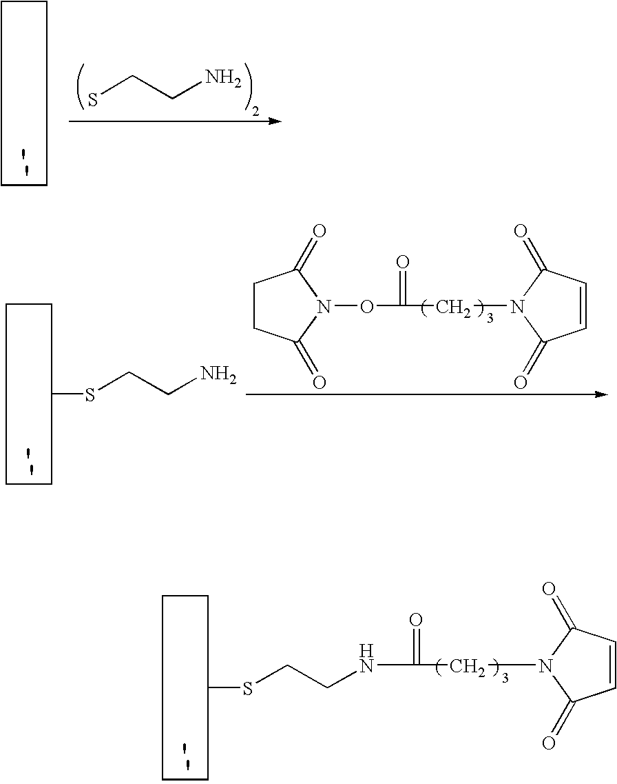
[0337]A base plate according to the present invention, comprising a glass slide coated with a thin (45 nm) layer of gold, was coated with a mixed self-assembled monolayer (SAM) containing 2% maleimide-terminal groups in a background of tri(ethylene glycol) terminal groups. This entire surface was then exposed to a 500-μM solution of a peptide (IpYGEFKKKC) that was phosphorylated on its tyrosine residue. This peptide reacted with the maleimide groups on the surface via its terminal cysteine group to yield a surface composed of 2% of a monolayer of phospho-peptide. A PDMS removable member comprising 10 well orifices was removably sealed to the base plate, and the phospho-peptide exposed by the well orifices was exposed to different concentrations of protein tyrosine phosphatase (PTP-1B) via the well orifices. The plate was then incubated at 37° C. for 30 minutes to allow the enzymatic cleavage of the phosphoryl group from the immobilized peptide by PTP-1B.

[0338]The PDMS removable memb...

example 2

[0340]A base plate according to the present invention, comprising a glass slide coated with a thin (45 nm) layer of gold, was coated with a mixed self-assembled monolayer (SAM) containing 2% maleimide-terminal groups in a background of tri(ethylene glycol) terminal groups. Solutions of seven tyrosine-containing peptides in a buffer solution were then arrayed onto the base plate using a robotic split-pin arrayer (PixSys 5500, Cartesian Technologies). The robot was programmed to create a rectangular 5×12 set of microarrays spaced by 4.5 mm, each microarray being composed of 4×4 100-μm spots (2 spots of each peptide and 2 of buffer) spaced by 300 μm. The peptides were then allowed to attach via their terminal-cysteine residues and the plate was washed in SDS and water.

[0341]A PDMS removable member according to the present invention that contained a set of 5×12 well orifices spaced by 4.5 mm was then aligned and sealed to the base plate so that each microarray had a liquid-tight well de...

example 3

[0343]Base plates according to the present invention, comprising glass slides coated with a thin (45 nm) layer of gold, were coated with a mixed self-assembled monolayer (SAM) containing 2% maleimide-terminal groups in a background of tri(ethylene glycol) terminal groups. These surfaces were then exposed to a 500-μM solution of a peptide (CEQEDEPEGIYGVLF) that is a good substrate for Lck kinase. The peptide reacted with the maleimide groups on the surface via its terminal cysteine group to yield a surface composed of 2% of a monolayer of peptide.

[0344]PDMS removable members comprising well orifices were removably sealed to the base plates, and the peptide exposed by the well orifices was exposed to different lysates of cell lines that over-express a kinase, ATP, and other co-factors. The plate was then incubated at 37° C. for 30 min to allow the enzymatic transfer of a phosphate group from ATP to the immobilized peptide by the kinase. The increase in phosphotyrosine in the well-bott...


PUM

PropertyMeasurementUnit
sizeaaaaaaaaaa
sizeaaaaaaaaaa
timeaaaaaaaaaa

Abstract

Devices and methods for performing assays on materials, particularly biological materials, are provided. The devices and methods make use of self-sealing members, which can be applied to a flat surface to form wells to facilitate immobilization of materials on the flat surface, then removed to yield a flat surface that facilitates thc performance of processes on and / or detection of the immobilized material.

Description

[0001]This application is a continuation-in-part of U.S. application 09 / 709,776 filed on Nov. 8, 2000, which issued as U.S. Pat. No. 6,699,665. This application also claims the benefit of priority of U.S. provisional application 60 / 307,839 (filed 27 Jul. 2001), 60 / 323,743 (filed 21 Sep. 2001), 60 / 357,649 (fled 20 Feb. 2002), 60 / 366,260 (filed 22 Mar. 2002) 60 / 375,024 (filed 25 Apr. 2002), 60 / 380,314 (filed 15 May 2002), and a continuation of PCT / US01 / 500909 (filed 7 Nov., 2001), and these applications are hereby incorporated by reference herein.FIELD OF THE INVENTION[0002]This invention relates generally to biological assays, and more particularly to devices and methods for arraying and / or assaying biological materials.BACKGROUND OF THE INVENTION[0003]There is a need to rapidly assay or screen potential drug candidates. Drug discovery is a long, multiple step process involving the identification of specific disease targets, development of assays based on a specific target, validatio...

Claims


Application Information

Patent Timeline
Patent Type & Authority Patents(United States)
IPC IPC(8): B01L3/00G01N33/543G06T7/00C40B40/06C40B40/10C40B60/14G01Q60/00
CPCB01L3/5025B01L3/5085B82Y5/00B82Y30/00C12M23/12C12Q1/025G01N33/54366G06T7/0012G06T7/004B01D2325/08B01J2219/00274B01J2219/00317B01J2219/00662B01J2219/00722B01J2219/00725B01J2219/00743B01L3/5027B01L2200/021B01L2200/025B01L2200/0647B01L2200/12B01L2300/0636B01L2300/0829B01L2300/0848B01L2300/0887B01L2300/123C40B40/06C40B40/10C40B60/14G01N15/1468G01N2015/1497G06T2207/10008G06T2207/10064G06T2207/30072G06T7/70
Inventor DUFFY, DAVIDKIRK, GREGORY L.CAMPBELL, STEWARTSCHUELLER, OLIVIERAGOSTO, MELINA
Owner SURFACE LOGIX INC
Learn More