
Method and device for moving subsea rocks and sediments

Inactive Publication Date: 2005-11-22
FOSSURA
View PDF38 Cites 17 Cited by
  • Summary
  • Abstract
  • Description
  • Claims
  • Application Information

AI Technical Summary

Benefits of technology

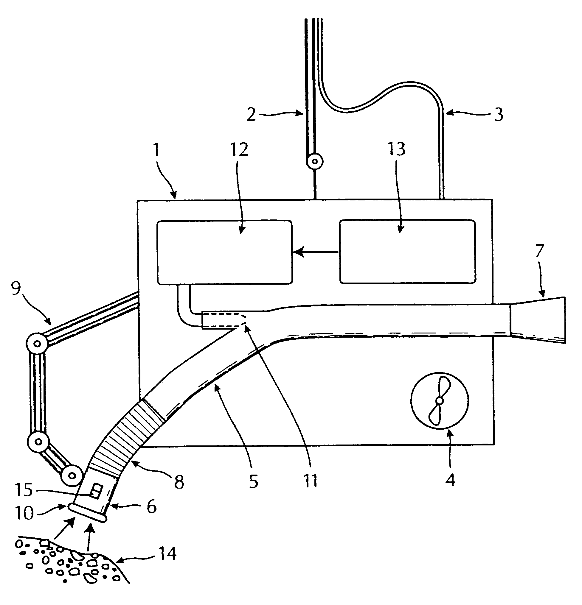
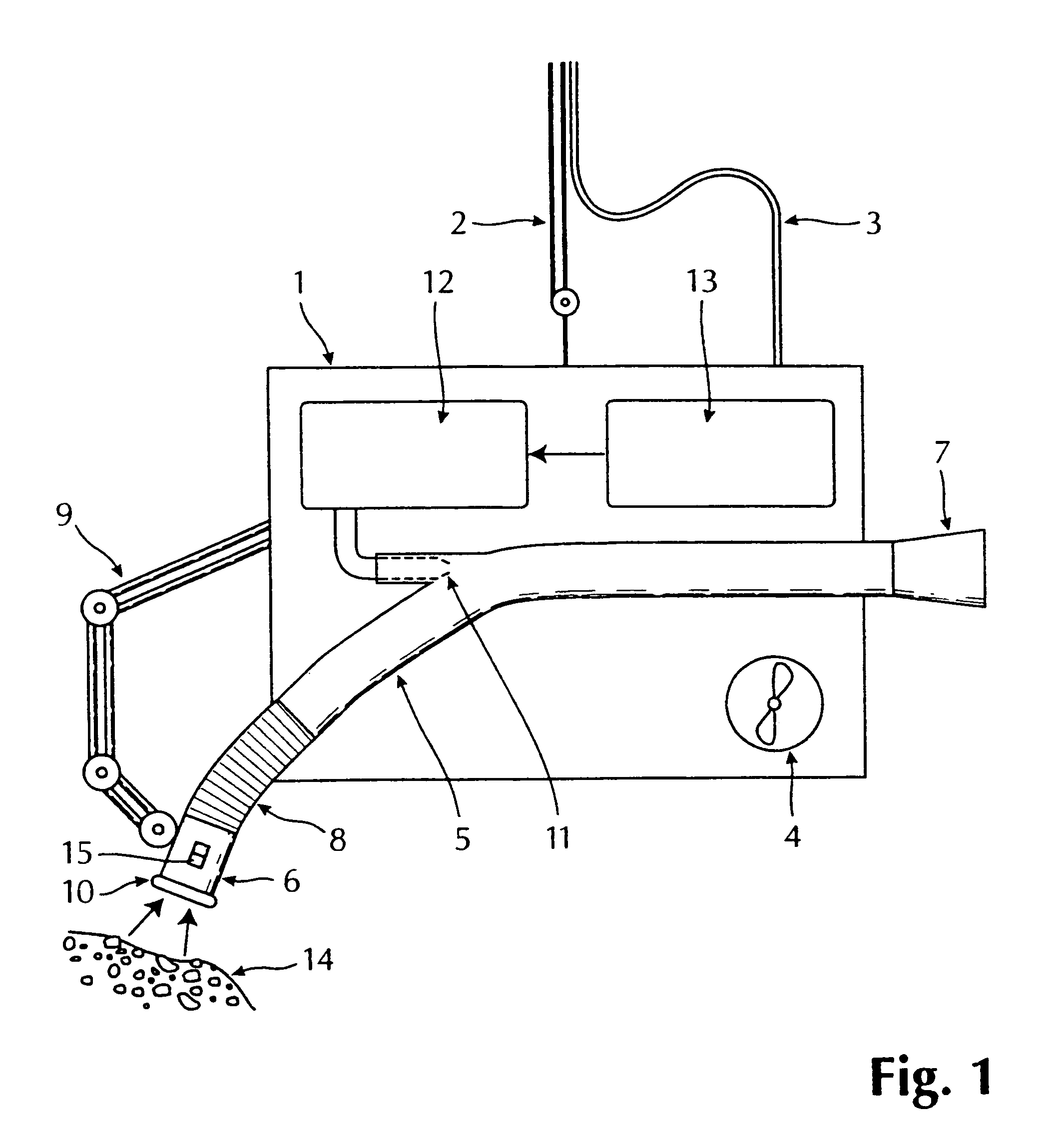
[0010]It is further an object to provide an apparatus for performing said method, which apparatus should be versatile in its use, especially in the way that it should be easy to move around down at the sea bottom.
[0011]It is still further an object to provide such an apparatus which is easy to control, and which does not require large amounts of energy to be supplied from the surface, but which can utilize the standard power supply available on an ROV.

Problems solved by technology

The most common way to remove sediments in connection with subsea work, is to utilize large “fans”, large and heavy suction devices with a high power consumption and specially designed excavators.
Disadvantages are that they require a lot of power and / or other resources, they require large surface vessels, have a limited versatility, are as good as stationary, or they are not at all suited for deep waters.
This apparatus is not suited to move sediments with relatively large rocks, mainly because the pipeline has an effective loss of diameter due to the ejector's design and position.
Furthermore it has geographically a very limited work range, as it is designed to rest at the sea bottom, even though the pipeline is supposed to be somewhat moveable.
From the abstract of these patent applications it is not possible to see what kind of utilizations these systems are intended for.

Method used


Image

  • Method and device for moving subsea rocks and sediments
  • Method and device for moving subsea rocks and sediments

Examples


example of practical embodiment

[0023]In a commission during the summer of 1999 1500 m3 of rocks (dmax=150 m) were moved with an apparatus according to the present invention. The commission took place in Tengsfjorden, at a pipeline for oil at a 540 m depth. An ROV of type Perry-XL was used. 100 l / min. of hydraulic oil at a pressure of 180 bar was available for running the water pump, which corresponds to 29 kW. The tubing, made from PE-plastic, had a total length of 10 m, and an internal diameter of 250 mm. Only a minimal wear could be observed on the tubing, It was observed, however, that rocks from time to time got stuck due to unintended unevenness in the tubing. The invention is unique in the sense that it allows rocks to be moved with much lighter equipment than that previously available on the market, and at depths where it has not been possible to conduct this kind of task. The above-referred commission confirms that the invention is practically feasible.


PUM


Abstract

A method for moving subsea rocks and sediments which can be at significant depths, in connection with removal of protective rocks around installations where maintenance is to be conducted. Tubing with an ejector nozzle is arranged completely externally in relation to the tubing on a standard, remote controlled submarine (ROV), so that the ejector nozzle produces a pressure gradient through the tubing. An inlet end of the tubing is located with the rocks and sediments to be moved, which are sucked into the tubing and blown out of the opposite end of the tubing.

Description

BACKGROUND OF THE INVENTION[0001]For work at subsea oil and gas installations or in connection with such installations, e.g. maintenance work, there is often a need to move rocks and particulate material that partly covers the body that is to be repaired. The body can be a pipeline, valve housing and the like.[0002]In a similar way it may arise a need to remove sediments in connection with new installations on the sea bottom, or for removal of accumulated drill cuttings at platforms or the like.[0003]Similar needs may also occur in connection with subsea work, such as at harbour works or barrage or quay structures.DESCRIPTION OF RELATED ART[0004]The most common way to remove sediments in connection with subsea work, is to utilize large “fans”, large and heavy suction devices with a high power consumption and specially designed excavators. Disadvantages are that they require a lot of power and / or other resources, they require large surface vessels, have a limited versatility, are as ...

Claims


Application Information

Patent Timeline
IPC IPC(8): B63C11/52E02B3/02E02B3/00E02F3/88E02F3/92E02F5/28E02F5/00
CPCB63C11/52E02B3/023E02F3/92E02F5/28Y02A10/00Y02A10/30
Inventor JACOBSEN, TOMFAGERVOLD, TERJEFAGERVOLD, GUNNERKVALVAAG, GUSTAV
Owner FOSSURA
Learn More