
Method for producing a hollow shaft, in particular a camshaft and a camshaft produced according to said method

a technology of camshafts and hollow shafts, which is applied in the direction of shafts, cams, vehicles/pulleys, etc., can solve the problems of increasing costs, and achieve the effects of short production times, improved connection to the hollow shaft, and reduced element diameter

Inactive Publication Date: 2005-11-08
LINAMAR ANTRIEBSTECHN
View PDF14 Cites 26 Cited by
  • Summary
  • Abstract
  • Description
  • Claims
  • Application Information

AI Technical Summary

Benefits of technology

[0021]It may also be advantageous to reduce the element in diameter between its two ends, as a result of which the connection to the hollow shaft is improved.
[0023]The advantage of the method according to the invention consists in the fact that two highly productive processes, internal high-pressure forming and upsetting, are combined at the same time in one process with the use of simple-to-produce machine elements to be connected to the hollow shaft. This results in very short production times.

Problems solved by technology

All of the known processes for producing elements connected to the hollow shaft for the purpose of coupling or mounting have the disadvantage in common that the process for producing and for connecting said elements to the shaft in a frictional and positive-locking manner requires at least one additional process step.
In addition, a machine fit is required, which in turn increases the cost.

Method used


Image

  • Method for producing a hollow shaft, in particular a camshaft and a camshaft produced according to said method
  • Method for producing a hollow shaft, in particular a camshaft and a camshaft produced according to said method

Examples


Embodiment Construction

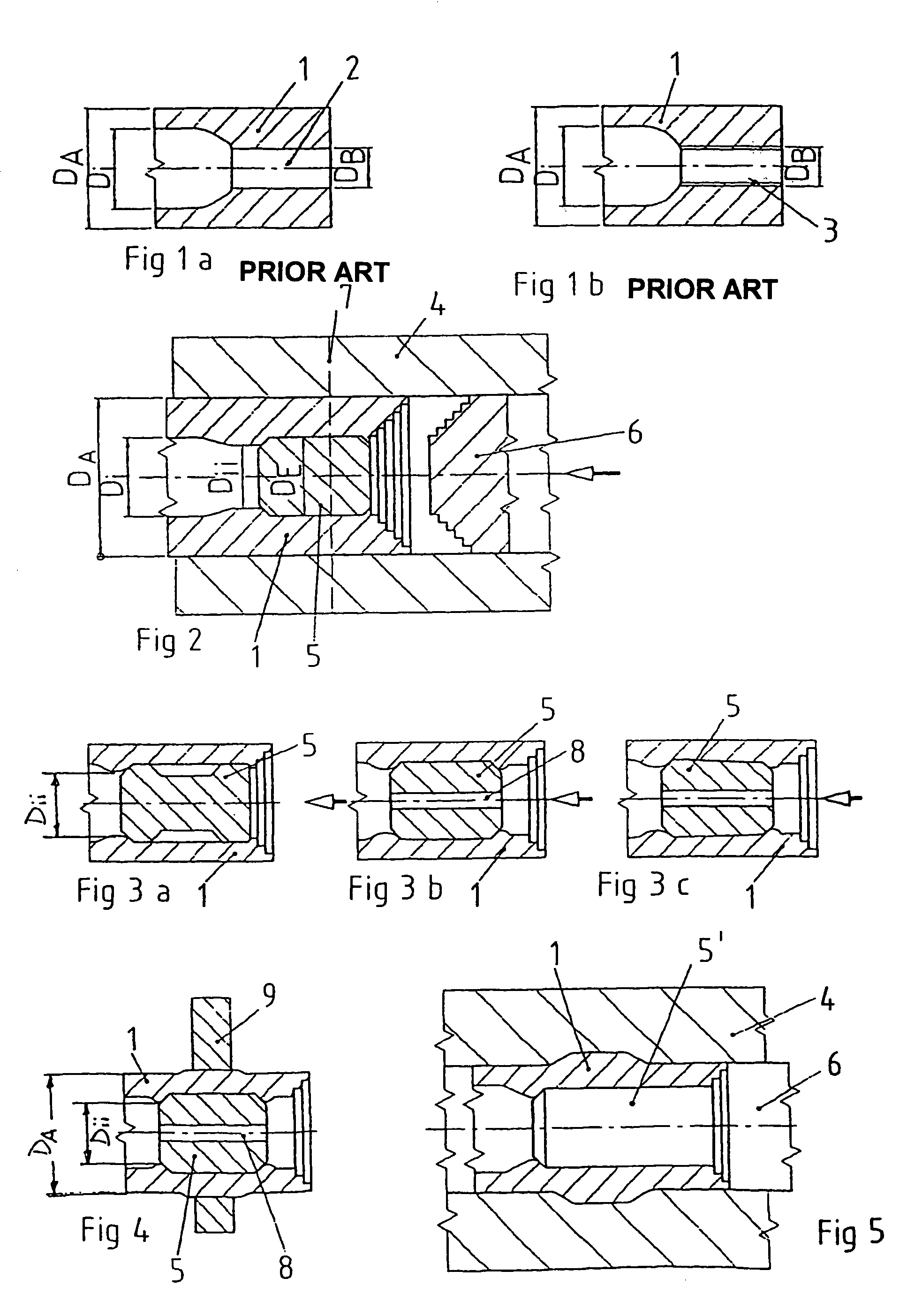
[0031]FIGS. 1a and 1b show how an end of a hollow shaft is produced according to the prior art. In the region of one of its ends, the hollow shaft 1 is treated according to a swaging process known per se or also by upsetting in such a way that, with a constant outside diameter DA of the hollow shaft 1, the inside diameter Di of the hollow shaft 1 is reduced to the diameter DB of a bore 2. This means that material accumulation is effected in the end region. This upsetting is effected by heating, hammering or even by another forming process. Either the bore 2 is incorporated during this process and then has to be mechanically reworked, or the end of the hollow shaft 1 is completely closed and the bore 2 or a thread 3 is then incorporated after the machining of the end face.

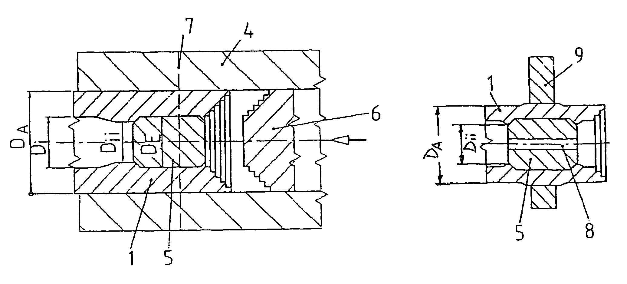
[0032]The method according to the invention is described with reference to FIG. 2. Inserted into a known IHF tool 4 is a hollow shaft 1, the outside diameter DA of which corresponds to the inside diameter of the too...


PUM

PropertyMeasurementUnit
Timeaaaaaaaaaa
Pressureaaaaaaaaaa
Diameteraaaaaaaaaa

Abstract

Hollow shafts, and particularly camshafts, are produced using an internal high-pressure forming (IHF) process. Cams and / or machine elements are mounted at intervals onto the outer surface of the hollow shaft, depending on the use of the latter, by a non-positive and / or positive fit, in a position appropriate to their function when the hollow shaft is placed in the forming tool. An element with approximately the same external diameter as the internal diameter of the hollow shaft is placed in at least one of the hollow shaft, and the hollow shaft together with the cams and / or machine elements that have been pushed onto the same and the inserted element are placed in an IHF tool. Once the IHF tool is closed, the medium is caused to act under the required high-pressure in the hollow shaft. At the same time as the medium is acting internally, at least one ram is pressed axially against at least one front face of the hollow shaft. Thus, filling the IHF mould with a material flow induced by the pressure effect of the medium and the mechanical pressure of the ram. The element is thus enclosed by the material of the hollow shaft and the cams and / or elements are connected to the hollow shaft by the non-positive and / or positive fit by means of the expansion of the hollow shaft. The end of the hollow shaft sealed by the element is mechanically machined to suit functional requirements.

Description

CROSS-REFERENCE TO RELATED APPLICATIONS[0001]Not applicableSTATEMENT REGARDING FEDERALLY SPONSORED RESEARCH OR DEVELOPMENT[0002]Not applicableINCORPORATION-BY-REFERENCE OF MATERIAL SUBMITTED ON A COMPACT DISC[0003]Not applicableBACKGROUND OF THE INVENTION[0004](1) Field of the Invention[0005]The invention relates to a method of producing a hollow shaft, in particular a camshaft, according to the internal high-pressure forming process (IHF), cams and / or machine elements being mounted on the outer lateral surface of the hollow shaft, in such a way as to be adapted to the use of the latter, in a frictional and / or positive-locking manner and so as to be distributed in functionally correct positions. The machine elements may be, for example, gears, drives, cam plates or the like. A preferred field of application is camshafts for motor vehicle engines.[0006](2) Description of the Related Art including information disclosed under 37 CFR 1.97 and 1.98[0007]It is known to produce camshafts f...

Claims


Application Information

Patent Timeline
IPC IPC(8): B21D26/02B21D39/04B21D26/00B21D53/84B21D53/00F01L1/04F01L1/047B21D26/033B21D39/00F16C3/02
CPCB21D26/033B21D39/04B21D53/845B23P11/005F01L1/047B23P2700/02Y10T403/4949Y10T29/49805Y10T29/17Y10T29/49938Y10T29/49293Y10T29/4994Y10T29/49911
Inventor FURCHHEIM, BODOSCHLEIFSTEIN, FRANZ-JOSEF
Owner LINAMAR ANTRIEBSTECHN
Learn More