
Automatic raman gain and tilt control for ultra-long-distance dense WDM optical communication system

a technology of optical communication system and automatic raman, applied in the field of optical communication system, can solve the problems of inability to precisely predict the behavior of distributed raman amplifier, the limitations of the bandwidth of existing communication system, and the inability to successfully implement these two amplifiers with each other, so as to minimize the non-linear effects of transmission fibers and increase signal-to-noise ratio performance, the effect of constant power

Inactive Publication Date: 2005-11-01
CISCO TECH INC
View PDF32 Cites 54 Cited by
  • Summary
  • Abstract
  • Description
  • Claims
  • Application Information

AI Technical Summary

Benefits of technology

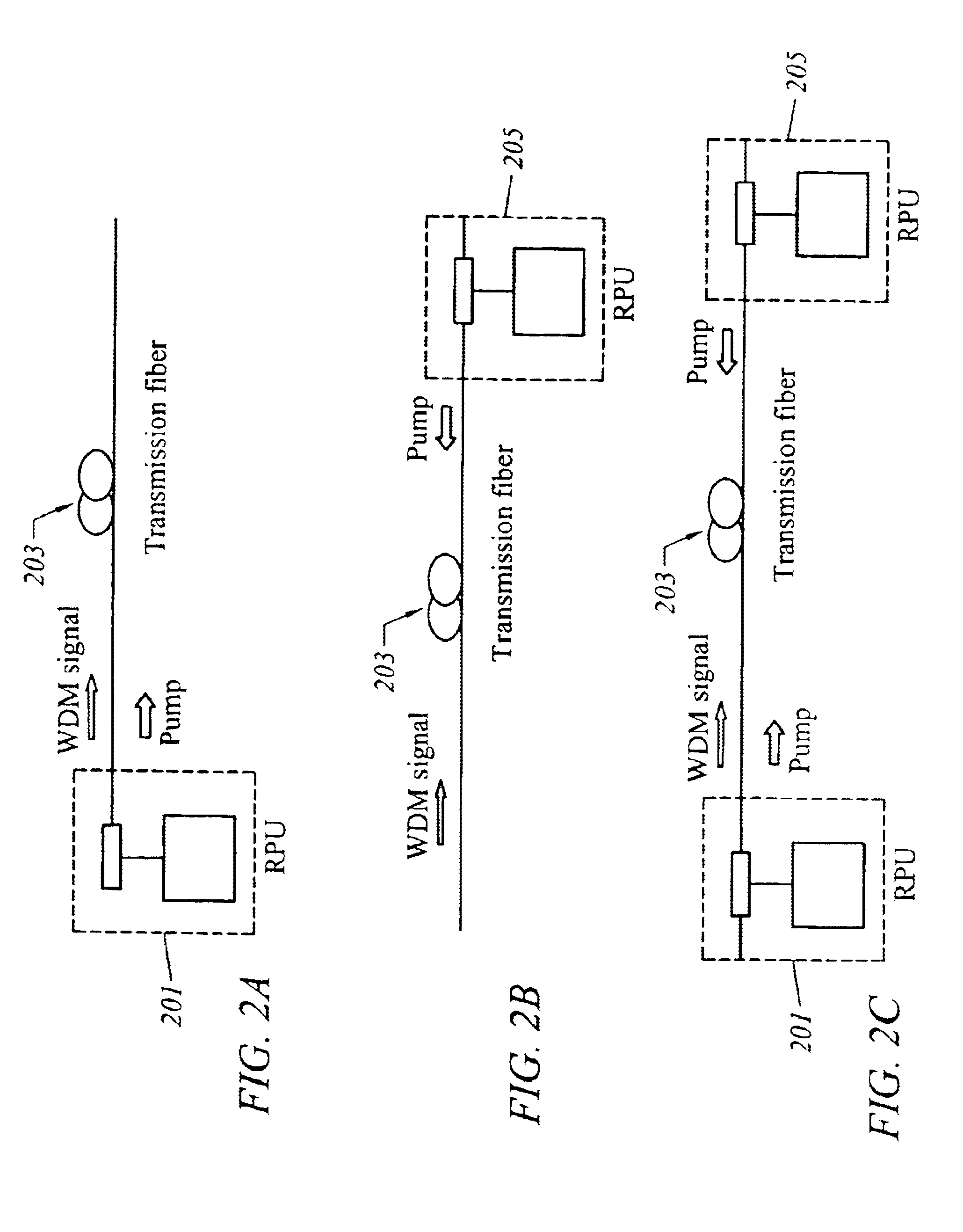
[0016]According to another aspect of the invention, a system for providing automatic gain and tilt control comprises an optical fiber that carries a plurality of optical signals, in which at least one of the optical signals is a reference signal. An optical gain unit is coupled to the optical fiber and is configured to output lights to compensate, in part, for losses associated with the optical fiber and gain tilt accumulation. A controller is configured to control the optical gain unit; the controller detects and analyzes the reference signals. The controller outputs a control signal to the optical gain unit based upon the analyzed reference signals to determine, in part, power variation of the reference signals. An optical Erbium doped fiber amplifier is coupled to the optical fiber and is configured to amplify the optical signals; the Raman optical gain unit provides nearly constant power per channel at an input of the optical amplifier. The above arrangement advantageously minimizes the non-linear effects of the transmission fibers.
[0017]According to yet another aspect of the invention, an optical device for providing automatic gain and tilt control in a WDM comprises an input that is coupled to an optical fiber. The input receives a plurality of reference signals. A plurality of photodiodes are configured to convert the reference signals to corresponding electrical signals. A controller is coupled to the photodiodes and is configured to output a control signal to at least one of a Raman pump unit or a variable optical attenuator for adjusting the reference signals to compensate, in part, for gain tilt and gain variation based upon the reference signals. The above arrangement advantageously increases signal-to-noise ratio performance.
[0018]According to yet another aspect of the invention, a WDM (wavelength division multiplexing) optical communication system for providing automatic gain and tilt control comprises an optical fiber that carries a plurality of optical signals, in which at least one of the optical signals is a reference signal. A light emitting means is coupled to the optical fiber for outputting lights to compensate, in part, for losses associated with the optical fiber and gain tilt accumulation. A controlling means controls the light emitting means; the controlling means detects and analyzes the reference signal to determine, in part, power variation of the reference signal. The controlling means outputs a control signal to the optical gain unit based upon the analyzed reference signal. An amplifying means is coupled to the optical fiber for amplifying the optical signals, wherein the light emitting means provides a constant power per channel at an input of the amplifying means. Under this approach, the non-linear effects of the optical communication system are minimized.

Problems solved by technology

However, this new mindset poses many challenges to the telecommunication industry to develop technology that will greatly expand the bandwidth limitations of existing communication systems.
However, there exists technical obstacles in the successful implementation of these two amplifiers with each other.
Specifically, the behavior of distributed Raman amplifiers cannot be precisely predicted because of the dependency of these amplifiers on the particular transmission fiber characteristics.
Such WDM systems are plagued with span losses, not to mention losses arising from add / drop operation and channel upgrades.
Thus, gain tilt and gain variation present substantial barriers to achieving a practical implementation of an ultra-long WDM system.
Even a small gain tilt or gain variation, which is locally introduced by the EDFA and / or DRA, can accumulate over very long distances, resulting in detrimental effects to the WDM system, such as increased bit-errors.
However, accumulated gain tilt and gain variation pose difficulty in the design of these filters.
Although a variety of gain control mechanisms have been developed for the EDFA, little work has been done for DRAs.
Traditional control mechanisms lack the flexibility to adapt to the operational conditions of the WDM system, as mentioned above.

Method used


Image

  • Automatic raman gain and tilt control for ultra-long-distance dense WDM optical communication system
  • Automatic raman gain and tilt control for ultra-long-distance dense WDM optical communication system
  • Automatic raman gain and tilt control for ultra-long-distance dense WDM optical communication system

Examples


Embodiment Construction

[0070]In the following description, for the purpose of explanation, specific details are set forth in order to provide a thorough understanding of the invention. However, it will be apparent that the invention may be practiced without these specific details. In some instances, well-known structures and devices are depicted in block diagram form in order to avoid unnecessarily obscuring the invention.

[0071]The present invention provides compensation for gain tilt accumulation in a WDM optical communication system. In particular, the gain and flatness of the distributed Raman amplifiers are controlled using two reference signals. This feature, combined with a suitable gain control scheme for the EDFA, allows the WDM system to be automatically adapted to different signals are positioned at the two boundaries of each sub-band. The reference signals can also coincide with transmitted signals within the system band. These reference signals are locally detected at each amplification site (...


PUM


Abstract

An approach for automatic Raman gain and tilt control for a WDM (Wavelength Division Multiplexing) optical communication systems is disclosed. An optical fiber carries a plurality of optical signals, in which at least one of the optical signals are reference signals. An optical gain unit (e.g., Raman pump unit) couples to the optical fiber and adjusts the reference signals to compensate, in part, for losses associated with the optical fiber and gain tilt accumulation. Upon detecting and analyzing the reference signals, a controller controls the optical gain unit and outputs a control signal to the optical gain unit based upon the analyzed reference signals. An optical amplifier is connected to the optical fiber and amplifies the optical signals. The optical gain unit provides a nearly constant power per channel at an input of the optical amplifier. Under this approach, a Raman gain control mechanism, combined with the use of gain controlled EDFA (Erbium Doped Fiber Amplifier), allows high transmission capacity over ultra-long distances without optical regeneration and with high flexibility.

Description

BACKGROUND OF THE INVENTIONField of the Invention[0001]The present invention relates to optical communication systems, and is more particularly related to providing automatic gain and tilt control for WDM (wavelength division multiplexing) optical communication systems.Discussion of the Background[0002]The explosion of communication services, ranging from video teleconferencing to electronic commerce, has spawn a new era of personal and business interactions. As evident in the enormous growth of Internet traffic, consumers have begun to embrace information technology, viewing it, in some cases, as much a necessity as the telephone. However, this new mindset poses many challenges to the telecommunication industry to develop technology that will greatly expand the bandwidth limitations of existing communication systems. Optical communications holds great promise to meet the continual demands for greater and greater bandwidth.[0003]Wavelength Division Multiplexing (WDM) technology, in ...

Claims


Application Information

Patent Timeline
Patent Type & Authority Patents(United States)
IPC IPC(8): H04J14/02H04B10/00H04B10/17
CPCH04B10/2916H04B10/2931H04J14/0221H04J14/02216
Inventor CASTAGNETTI, ROBERTADI PASQUALE, FABRIZIOGRASSO, GIORGIOMELI, FAUSTOSACCHI, GIOVANNI
Owner CISCO TECH INC
Learn More