
Hammer with high pressure shut-off

a vibrator and high-pressure technology, applied in the field of fluid-powered impact vibrators, can solve problems such as interruption of the energy supply of the impact vibrator

Inactive Publication Date: 2005-11-01
KRUPP BERCO BAUTECHN
View PDF12 Cites 14 Cited by
  • Summary
  • Abstract
  • Description
  • Claims
  • Application Information

AI Technical Summary

Benefits of technology

[0013]Due to the fact that the pressure shut-off valve or the pressure-limiting valve as a component of the guide unit or the percussion hammer itself, meaning as a component of the impact vibrator, is effective in stopping the percussion hammer, if necessary, the impact vibrator can be used without retrofitting for construction machinery that is designed such that the input power varies. Accordingly, the impact vibrator is ready for operation at the location of use, without requiring a retrofitting that may be necessary to avoid possible excess stress.
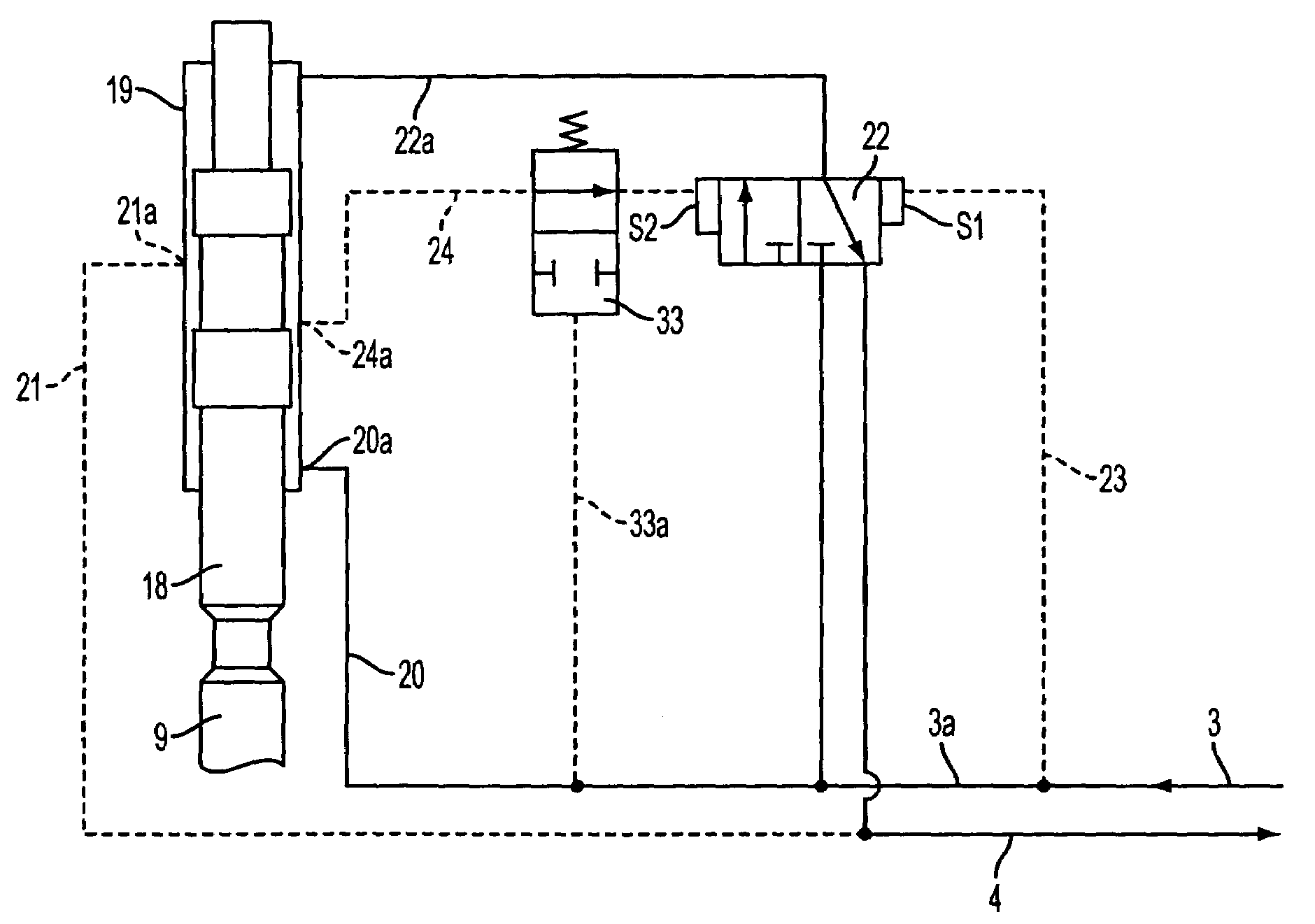
[0014]Within the framework of the invention, the pressure shut-off valve or the pressure-limiting valve in particular can also be a component of and can be integrated into the percussion hammer itself. Should the operating pressure acting upon the impact vibrator via the intermediate pressure shut-off valve have or assume an unacceptably high value, the pressure shut-off valve is moved automatically to the blocked position, which causes an interruption in the energy supply to the impact vibrator. In order to restart the impact vibrator, it is only necessary to adapt the respective input power supplied by the supply unit, e.g., by reducing the speed of the associated pump unit.

Problems solved by technology

Should the operating pressure acting upon the impact vibrator via the intermediate pressure shut-off valve have or assume an unacceptably high value, the pressure shut-off valve is moved automatically to the blocked position, which causes an interruption in the energy supply to the impact vibrator.

Method used


Image

  • Hammer with high pressure shut-off
  • Hammer with high pressure shut-off
  • Hammer with high pressure shut-off

Examples


Embodiment Construction

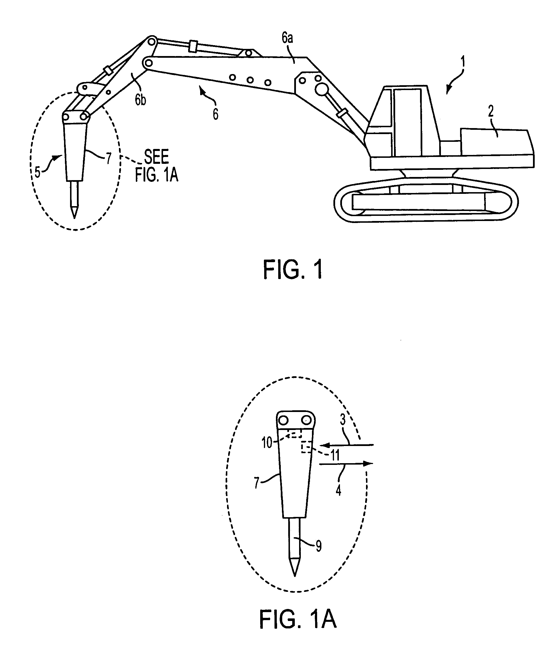
[0031]The fluid-powered excavator 1, shown in FIG. 1, is provided with a supply unit 2 (comprising essentially a non-shown diesel motor and a fluid-powered pump operated by this diesel motor) which, e.g., as known from the German reference DE 40 36 918 A1, is connected via a pressure line 3 and a non-pressurized return-flow line 4 (See also FIG. 1a) to a fluid-powered impact vibrator 5. The vibrator 5 is held with two jib arms or booms 6a, 6b on the jib 6 of the fluid-powered excavator, such that it can be turned on.

[0032]A support frame 7 functions as a guide unit for the impact vibrator 5 and is attached such that it can be tilted with respect to the jib 6b. A fluid-powered percussion hammer 8, e.g., as shown in FIG. 3, is supported on this frame 7.

[0033]A tool in the form of a chisel 9 projects from the support frame 7, upon which the percussion hammer acts in the known manner.

[0034]The diagram in FIG. 1a furthermore shows that the impact vibrator 5 has a control means (arrangeme...


PUM

PropertyMeasurementUnit
Pressureaaaaaaaaaa

Abstract

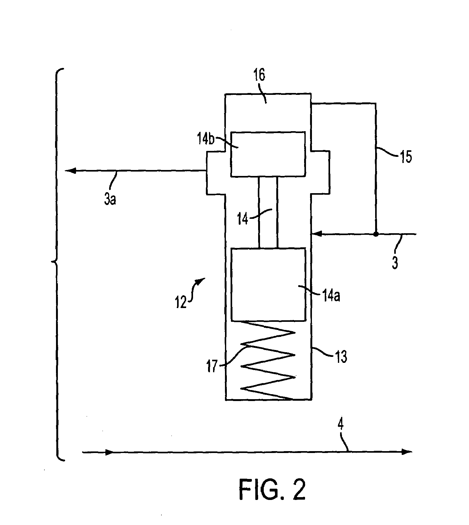
A fluid-powered impact vibrator (5), in particular a hydraulic hammer, comprising a fluid-powered percussion hammer (8) with a percussion piston (18) that is moved back and forth under the effect of a control means (10) and comprising a guide unit (7) on which the percussion hammer is supported, wherein the impact vibrator is additionally provided with a control valve, designed as a pressure monitor, for adaptation to the supplied input power. The control valve preferably is a pressure shut-off valve or a pressure-limiting valve (25) that is connected to the input pressure line (3) provided with the operating pressure, and automatically stops the percussion hammer (8) if the operating pressure resulting from the input power exceeds a specified maximum value. To stop the percussion hammer (8), either the pressure line (3) is blocked or the control means (10) is held in one of its end positions, i.e., the operating stroke or the return stroke positions. Moreover, the pressure shut-off valve or the pressure-limiting valve (25) preferably is a component of the guide unit, consisting of a support frame (7), or the percussion hammer (8) itself.

Description

REFERENCE TO RELATED APPLICATIONS[0001]This application claims the priority of German application Serial No. DE 19803449.8, filed Jan. 30, 1998, which is incorporated herein by reference.BACKGROUND OF THE INVENTION[0002]The invention relates to a fluid-powered impact vibrator, in particular a hydraulic hammer, comprising a fluid-powered percussion hammer or striking tool with a percussion piston, the back and forth movement of which is effected by a control arrangement, as well as a guide unit on which the percussion hammer is supported, and wherein the impact vibrator is additionally provided with a control valve, designed to function as a pressure monitor for adapting the system to the supplied input power.[0003]Fluid-powered impact vibrators—used in particular for crushing rock, concrete or other building materials—for the most part are used as accessory units or attachments for construction machinery, e.g., excavators, loaders or other basic equipment.[0004]Such an application c...

Claims


Application Information

Patent Timeline
IPC IPC(8): B25D9/26B25D9/00B25D17/10E21B1/26
CPCB25D9/26
Inventor PROKOP, HEINZ-JURGENGEIMER, MARCUS
Owner KRUPP BERCO BAUTECHN
Learn More