
Virtual telephone

a virtual telephone and communication system technology, applied in the field of virtual telephones, can solve the problems of virtually impossible to integrate one vendor's switching device with another vendor's application, inability to provide a generic interface between many possible proprietary protocols of different pbx switching systems and an external application, and inability to convert proprietary/pbx or external application protocols into a common forma

Inactive Publication Date: 2005-10-18
INTEL CORP
View PDF6 Cites 0 Cited by
  • Summary
  • Abstract
  • Description
  • Claims
  • Application Information

AI Technical Summary

Benefits of technology

[0015]When a packet is received from a switch, an abstraction layer parses the data and calls an internal VPAPI function. The internal VPAPI function is responsible for updating the virtual phone structure and passing the information about any state changes to an auxiliary PC through the virtual phone host interface. An internally designed protocol is used to provide communication b...

Problems solved by technology

Even though today most vendors build the PBXs around common available processors running common operating systems (such as UNIX) and use common programming languages (such as C or C++), unfortunately different vendors' switching devices use proprietary communication protocols.
Thus, it is virtually impossible to integrate one vendor's switching device with other vendors' applications.
An obvious disadvantage of the disclosed system is its inability to provide a generic interface between many possible proprietary protocols of different PBX switching systems and an external application.
The disclosed adapter does not, however, convert proprietary / PBX or external application protocols into a common format and thus does not function as a protocol interpreter between proprietary switching system protocols and the protocols of various applications.
That device, again, provides no more than a communication tool between a PBX switch and a voice mail system.

Method used


Image

  • Virtual telephone
  • Virtual telephone
  • Virtual telephone

Examples


Embodiment Construction

Telephone Communication System

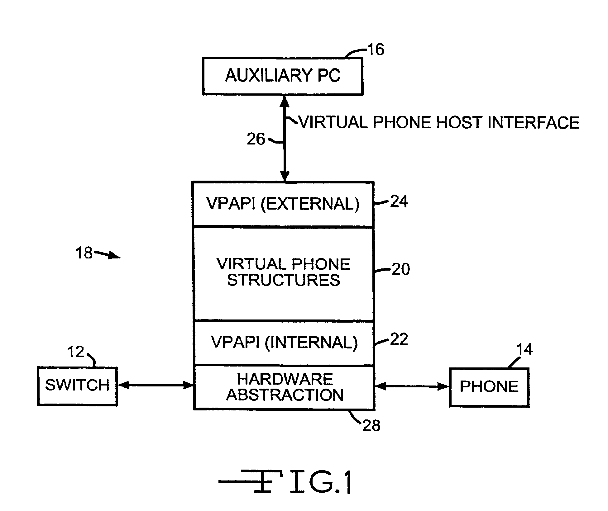
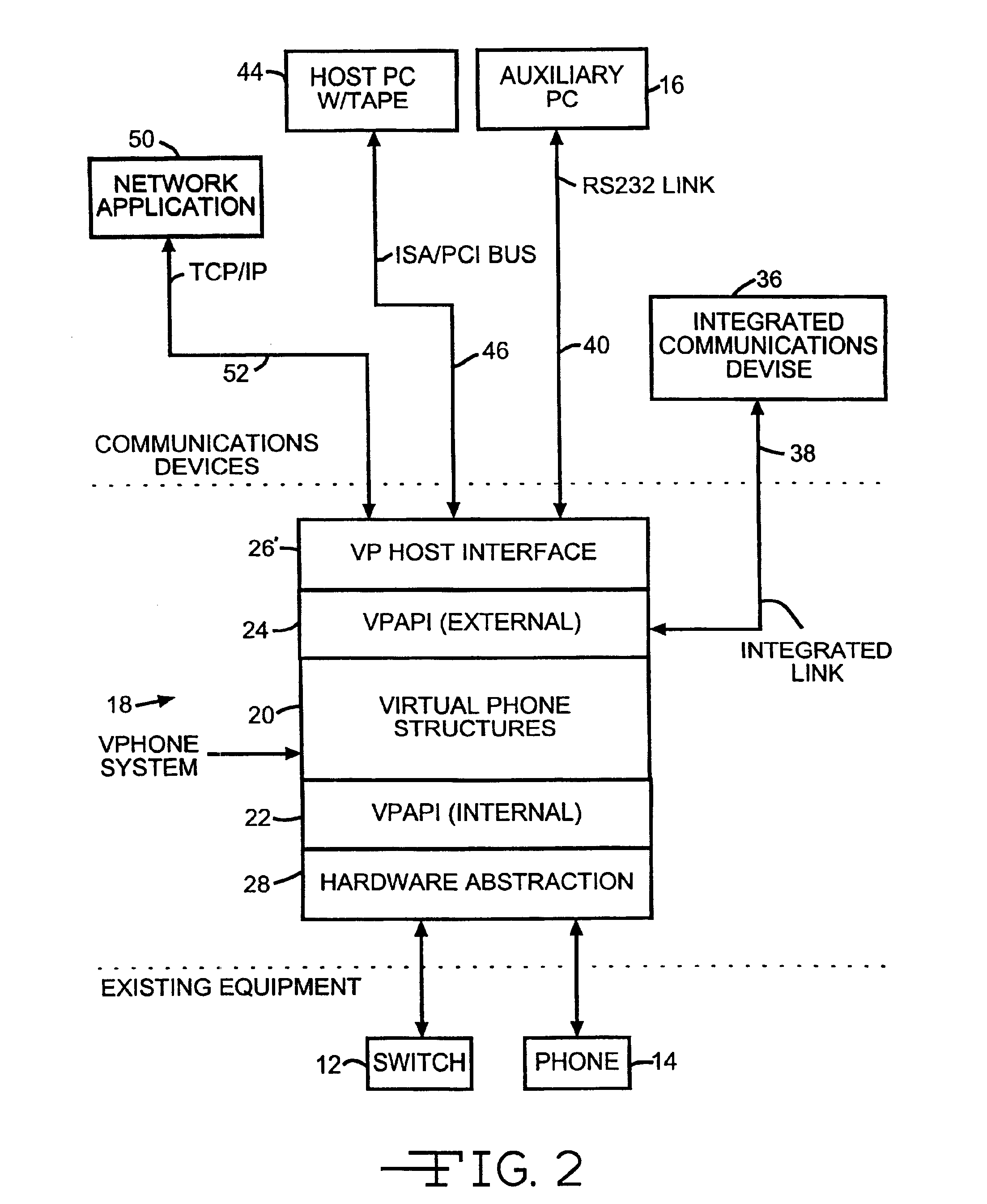
[0023]A telephone communication system utilizing the virtual phone of the present invention is shown in FIG. 1 wherein a PBX or similar digital switching device 12, a digital telephone 14 and an external device such as a personal computer (PC) or other processor 16 are interfaced by the arrangement 18 of the present invention. The virtual phone generic interface 18 of the present invention comprises a set 20 of virtual phone data structures, internal and external virtual phone application program interfaces 22 and 24, respectively, and a virtual phone host interface 26. Software designated hardware abstraction layer 28 provides communication between the internal virtual phone application program interface 22, PBX 12 and the telephone set 14.

[0024]Switch 12 can be a PBX, KSU, service provided by a central office (such as Centrex or ISDN) and does not even have to digital. Digital telephone 14 is representative of other communication devices like phones u...


PUM


Abstract

A telephone communication system utilizing a virtual phone wherein a telephone switch or similar digital switching device, a digital telephone and an external device such as a personal computer (PC) or other processor are generically interfaced. The virtual phone generic interface is configurable and comprises a set of virtual phone data structures, internal and external virtual phone application program interfaces, and an external transfer protocol. Software designated an abstraction layer provides communication between the internal virtual phone application program interface, the telephone switch and the telephone set. The generic interface converts proprietary telephone switch or external interface application protocols into a common format and functions as a protocol interpreter between proprietary switching system protocols and protocols of various applications.

Description

[0001]This application is a continuation of U.S. Ser. No. 09 / 057,681 filed Apr. 9, 1998, now U.S. Pat. No. 6,208,724.BACKGROUND OF THE INVENTION[0002]1. Field of the Invention[0003]The present invention relates generally to a telephone communication system and, in particular, to a device that provides a generic software interface to a digital line on one of many different types of digital phone switches. A telephone with such a generic interface is a “virtual phone” that has the flexibility to represent the majority of features of any digital phone, regardless of the switch type or the number of features in a digital phone.[0004]The general concept of a virtual telephone has been in existence in various forms across different product lines. In some cases a virtual phone has been used to represent a specific digital phone, such as Rolm Phone 400 or a Meridian 2616. Those phones represent a superset of phones for their respective switches. In other cases a virtual phone has been used ...

Claims


Application Information

Patent Timeline
IPC IPC(8): H04Q3/545H04M11/00H04Q3/62H04M3/42H04M3/00H04Q3/42
CPCH04M3/42314H04M3/42323H04M11/00H04Q3/54516H04Q3/54583H04Q3/62H04M1/2535H04Q2213/13003H04Q2213/1305H04Q2213/13093H04Q2213/13098H04Q2213/13106H04Q2213/13109H04Q2213/13196H04Q2213/13204H04Q2213/13209H04Q2213/13216H04Q2213/1322H04Q2213/13222H04Q2213/1329H04Q2213/13299H04Q2213/13362H04Q2213/13389
Inventor FRITZINGER, ROBERTOLSEN, RONALD D.
Owner INTEL CORP
Learn More