Disk-shaped antenna with polarization adjustment arrangement

a disk-shaped antenna and polarization adjustment technology, applied in the direction of resonant antennas, antenna earthings, radiating element structural forms, etc., can solve the problems of difficult to precisely control the design parameters in the manufacturing process, the characteristic properties of the produced disk-shaped antenna are typically not the same as desired or even completely cannot meet the requirement, and the time-consuming and labor-intensive procedur

Active Publication Date: 2005-10-18
TAIWAN GREEN POINT ENTERPRISE
View PDF4 Cites 26 Cited by
  • Summary
  • Abstract
  • Description
  • Claims
  • Application Information

AI Technical Summary

Benefits of technology

[0007]In one aspect of the present invention an angle between two metal bands is adapted to change by rotating one about the other for adjusting current loop and potential difference in an electric field perpendicular to the plane of the metal loop, thereby controlling the spiral of electromagnetic wave transmitted from the disk-shaped antenna. By configuring as above, the angle between the metal bands is adapted to change so as to design a disk-shaped antenna having different spirals of electromagnetic wave for overcoming the drawback (e.g., without adaptability) of the prior disk-shaped antenna.

Problems solved by technology

However, design parameters are difficult of being precisely controlled in the manufacturing process.
As a result, properties of the produced disk-shaped antenna are typically not the same as desired or even completely cannot meet the requirement.
This is a time consuming and labor intensive procedure.
As a result, the manufacturing cost is increased greatly and thus mass production is made impossible.
This inevitably can adversely increase inventory and cost.

Method used


Image

  • Disk-shaped antenna with polarization adjustment arrangement
  • Disk-shaped antenna with polarization adjustment arrangement
  • Disk-shaped antenna with polarization adjustment arrangement

Examples


Embodiment Construction

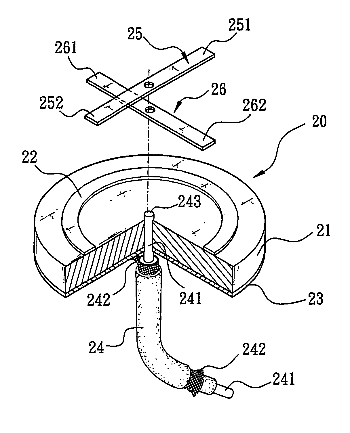
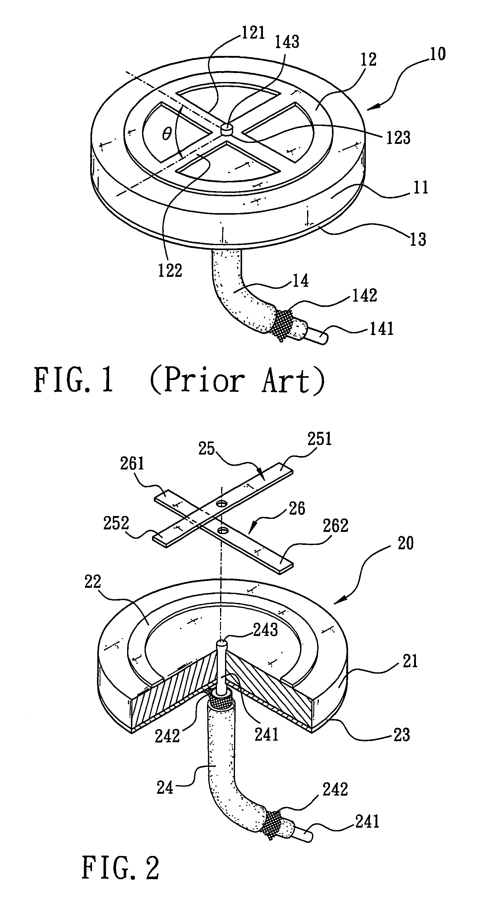
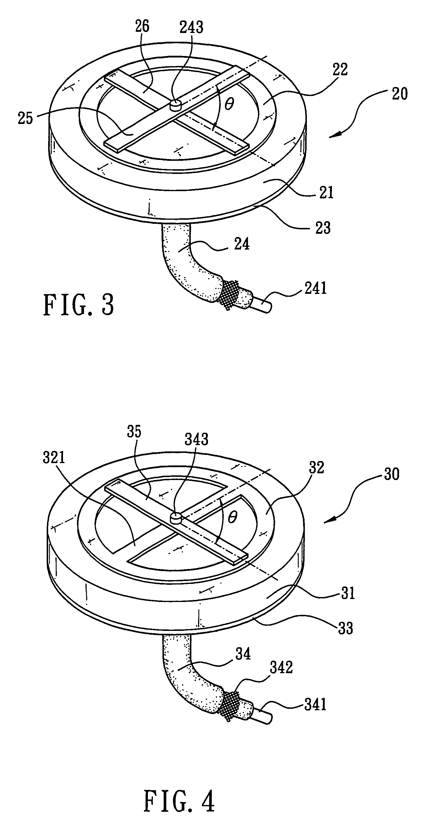
[0013]Referring to FIG. 2, there is shown a disk-shaped antenna 20 according to a first preferred embodiment of the invention. The disk-shaped antenna 20 comprises a dielectric substrate 21 formed of ceramic material, a hollow ring-shaped metal loop 22 formed on top of the substrate 21 by carrying out photolithography and etching, and a ground metal face 23 formed on bottom of the substrate 21 by carrying out photolithography and etching. A hole is provided in about center of each of the substrate 21 and the ground metal face 23. A coaxial 24 has a central conductor 241 inserted through the holes from bottom to top so as to expose its end 243 and which is in turn connected to at least two rotatable metal bands. The rotatable metal bands are designated by references numerals 25 and 26 and are intersected each other shown in the preferred embodiment of FIG. 2 as described below. Length of each of the metal bands 25 and 26 is slightly larger than an inner diameter of the metal loop 22....


PUM


Abstract

The present invention is to provide a disk-shaped antenna comprising a ring-shaped metal loop and a ground metal face respectively on top and bottom of a substrate, wherein a center hole is provided in each of the substrate and the ground metal face, a central conductor of a coaxial is inserted through the holes and connected to at least one rotatable metal band on the top of the substrate, two ends of the metal band are adapted to contact the metal loop, and braided outside conductor of the coaxial contacts the ground metal face. Thus, an angle between two metal bands is adapted to change by rotating one about the other for adjusting current loop and potential difference in an electric field perpendicular to the plane of the metal loop, thereby controlling the spiral of electromagnetic wave transmitted from the disk-shaped antenna.

Description

FIELD OF THE INVENTION[0001]The present invention relates to antennas, more particularly to a disk-shaped antenna having a central conductor of a coaxial connected to at least one rotatable metal band on the top of a substrate, where an angle between two metal bands is adapted to change by rotating one about the other for controlling the spiral of electromagnetic wave transmitted from the disk-shaped antenna.BACKGROUND OF THE INVENTION[0002]Conventionally, a disk-shaped antenna is mounted in a device with GPS (Global Positioning System). The disk-shaped antenna is advantageous for being small and robust, having high heat resistance and low power loss, and being highly adapted to mount on a curved surface of a member. FIG. 1 shows a disk-shaped antenna 1 mounted in a cellular phone with GPS or GSM (Global System for Mobile communications) feature. The disk-shaped antenna 10 comprises a dielectric substrate 11 formed of ceramic material, a ring-shaped metal loop 12 formed on top of th...

Claims


Application Information

Patent Timeline
Patent Type & Authority Patents(United States)
IPC IPC(8): H01Q1/38H01Q7/00
CPCH01Q1/38H01Q7/00H01Q9/0464
Inventor CHEN, CHUN-HAO
Owner TAIWAN GREEN POINT ENTERPRISE
Why Eureka
Try Eureka