
Antenna system for terrestrial broadcasting

a technology for terrestrial broadcasting and antennas, applied in television systems, instruments, teaching apparatus, etc., can solve the problems of difficult to determine the size of an antenna, the space restriction of the indoor antenna for receiving vhf-h signals including digital broadcast signals, etc., and achieve the effect of preventing electrostatic discharg

Inactive Publication Date: 2005-09-27
SAMSUNG ELECTRONICS CO LTD
View PDF10 Cites 11 Cited by
  • Summary
  • Abstract
  • Description
  • Claims
  • Application Information

AI Technical Summary

Benefits of technology

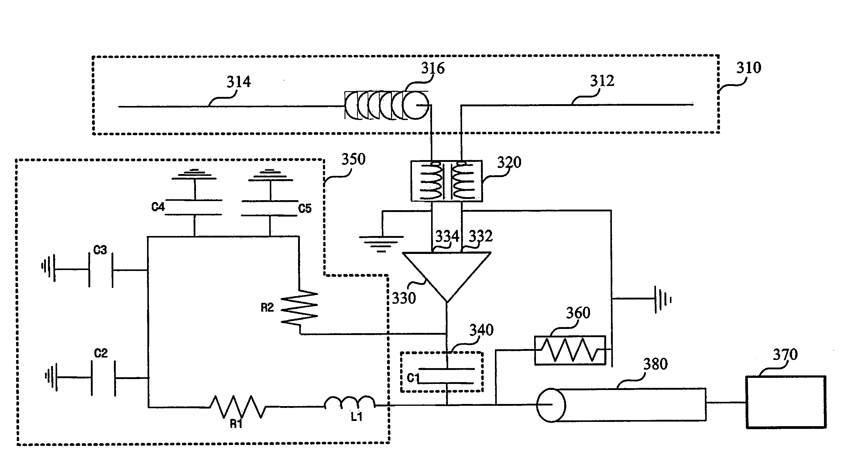
[0011]The present invention provides an antenna system designed to maximize signal propagation by compensating for an electrical length of an antenna probe by adding an inductor to the antenna probe and achieving wideband impedance matching between the antenna probe and a signal amplifier.
[0016]Further, the signal amplifier may comprise a monolithic microwave integrated circuit (MMIC) reducing noise contained in the received broadcast signal and amplifying the received broadcast signal.
[0021]In another preferred embodiment of the present invention, the antenna system may further comprise a circuit protector for maintaining the power supplied from the broadcast receiver substantially constant and preventing electrostatic discharge. In this case, the circuit protector may comprise an arrestor.

Problems solved by technology

However, an indoor antenna for receiving a VHF-H signal including a digital broadcast signal is subject to space restrictions.
Due to the space restrictions, it is difficult to determine the size of an antenna that varies according to a frequency band and realizes a dipole antenna.

Method used


Image

  • Antenna system for terrestrial broadcasting
  • Antenna system for terrestrial broadcasting
  • Antenna system for terrestrial broadcasting

Examples


Embodiment Construction

[0028]Advantages and features of the present invention and methods of accomplishing the same may be understood more readily by reference to the following detailed description of preferred embodiments and the accompanying drawings. The present invention may, however, be embodied in many different forms and should not be construed as being limited to the embodiments set forth herein. Like reference numerals refer to like elements throughout the specification.

[0029]FIG. 3 is a block diagram of an antenna system according to an embodiment of the present invention. Referring to FIG. 3, the antenna system 300 according to an embodiment of the present invention comprises an antenna probe 310 that receives a broadcast signal, an antenna matching unit 320 that performs impedance matching between the antenna probe 310 and a low noise amplifier 330, the low noise amplifier 330 that amplifies the broadcast signal in such a manner as to minimize noise contained in the broadcast signal and maximi...


PUM


Abstract

Provided is an antenna system for terrestrial broadcasting. The antenna system has a dipole antenna probe receiving a broadcast signal, a signal amplifier amplifying the received broadcast signal, an antenna matching unit matching impedances between the antenna probe and the signal amplifier, an output matching unit matching impedances between an output signal of the signal amplifier and an input terminal of a broadcast receiver to which the output signal is fed, and a bias extractor converting power received from the broadcast receiver into power needed for driving the signal amplifier and supplying the converted power to the signal amplifier.

Description

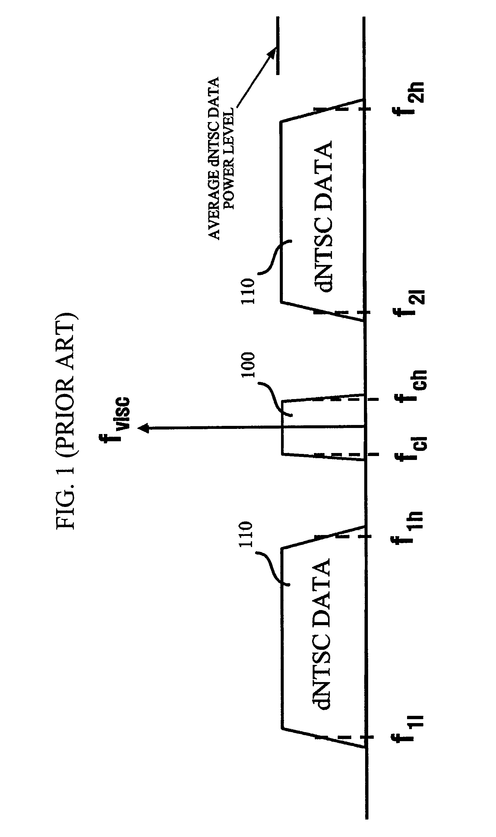
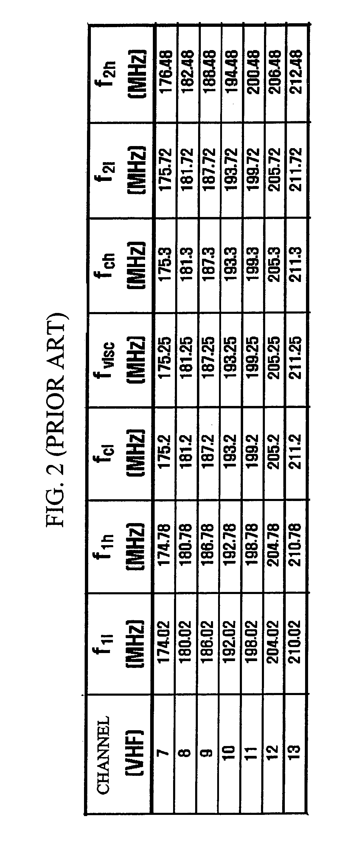
CROSS-REFERENCE TO RELATED APPLICATION[0001]This application claims priority from Korean Patent Application No. 10-2004-0024145 filed on Apr. 8, 2004 in the Korean Intellectual Property Office, the disclosure of which is incorporated herein by reference in its entirety.BACKGROUND OF THE INVENTION[0002]1. Field of the Invention[0003]The present invention relates to an antenna system, and more particularly, to an antenna system for terrestrial broadcasting designed to receive a television (TV) broadcast signal and deliver the television (TV) broadcast signal.[0004]2. Description of the Related Art[0005]While a National Television Systems Committee (NTSC) standard is an analog TV broadcast standard used today in North America, an Advanced Television Systems Committee (ATSC) standard is a digital TV broadcast standard. Broadcasts adopting a new technology called data in NTSC video (dNTSC) to embed a digital signal into the existing NTSC TV frequency range are being made over a Very High...

Claims


Application Information

Patent Timeline
Patent Type & Authority Patents(United States)
IPC IPC(8): H01Q23/00H01Q9/04H01Q9/28H01Q1/32H01Q9/16H03H7/38H04B1/18H04N5/44H04N5/63
CPCH01Q9/16H04B1/18G09B19/18A45C1/06B43K23/002
Inventor BAE, BUM-YOUL
Owner SAMSUNG ELECTRONICS CO LTD
Learn More