Capacitor discharge ignition device
a technology of capacitor discharge and ignition device, which is applied in the direction of ignition safety means, electric control, machines/engines, etc., can solve the problems of complex circuit configuration, device cost, and inability to ignite combustion engines, and achieve the effect of simple circuit configuration
- Summary
- Abstract
- Description
- Claims
- Application Information
AI Technical Summary
Benefits of technology
Problems solved by technology
Method used
Image
Examples
embodiment 1
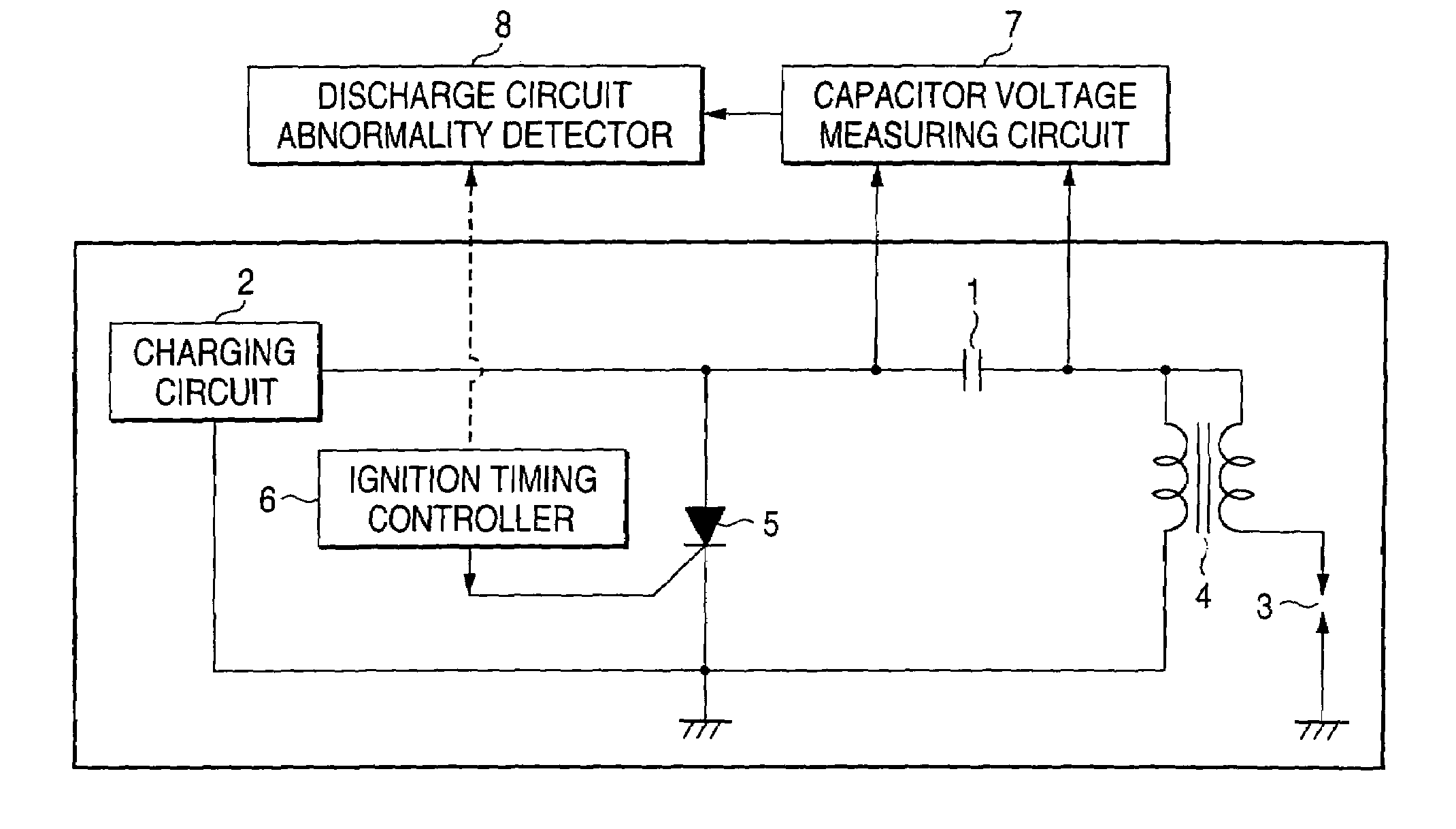
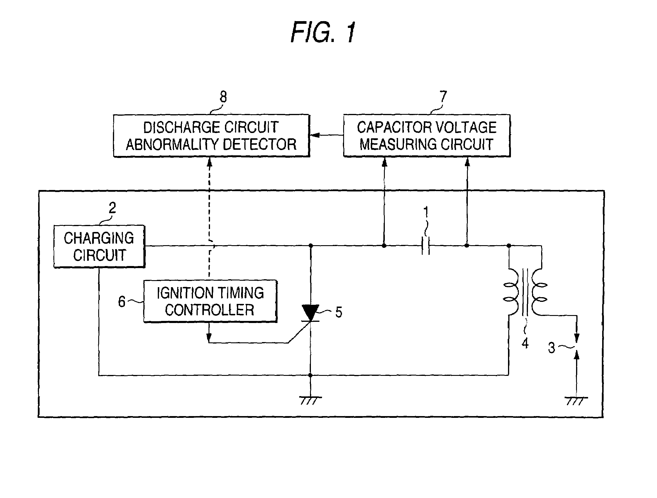
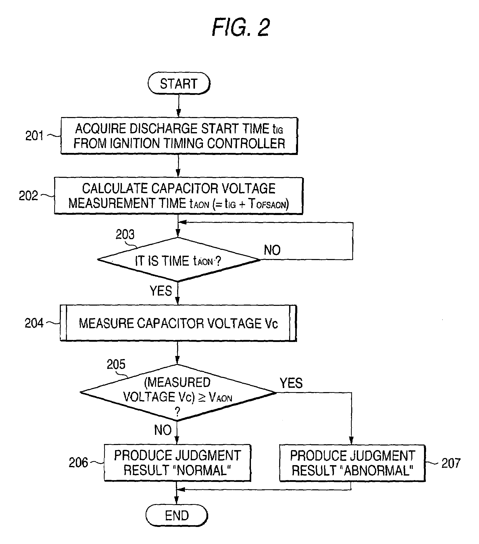
[0017]FIGS. 1–3 are for description of a capacitor discharge ignition device according to a first embodiment of the present invention. More specifically, FIG. 1 is a circuit diagram showing the configuration of the capacitor discharge ignition device and FIGS. 2 and 3 are a flowchart and a time chart, respectively, showing its operation. As shown in FIG. 1, the capacitor discharge ignition device according to this embodiment is composed of a capacitor 1 for storing charge to produce ignition energy, a charging circuit 2 as a DC power source for charging the capacitor 1, ignition coils 4 connected to an ignition plug 3, a switching element 5 for supplying the charge stored in the capacitor 1 to the primary side of the ignition coils 4, an ignition timing controller 6 for determining ignition timing on the basis of a received crank angle signal of an internal combustion engine and producing a signal for driving the switching element 5 at an ignition time, a capacitor voltage measuring...
embodiment 2
[0023]FIGS. 4A and 4B and FIG. 5 are flowcharts and a time chart, respectively, showing the operation of a capacitor discharge ignition device according to a second embodiment of the invention. In the capacitor discharge ignition device according to this embodiment, unlike in the case of the first embodiment, the timing for measuring and judging a capacitor voltage is determined by using the crank angle signal that is input to the ignition timing controller 6 without calculating a measurement time. It is intended to obtain the same advantages as of the first embodiment with a simpler configuration. Whereas the circuit configuration is the same as shown in FIG. 1, not only the ignition signal that is produced on the basis of the crank angle signal generated by a crank angle sensor but also the crank angle signal as a timing signal for voltage measurement is input from the ignition timing controller 6 to the discharge circuit abnormality detector 8. This will be described below with r...
embodiment 3
[0027]FIGS. 6–8 are for description of a capacitor discharge ignition device according to a third embodiment of the invention. More specifically, FIG. 6 is a circuit diagram showing the configuration of the capacitor discharge ignition device and FIGS. 7 and 8 are a flowchart and a time chart, respectively, showing its operation. The capacitor discharge ignition device according to this embodiment is different from that according to the first embodiment in that the former detects an abnormality in the charging circuit 2 and the discharge circuit for the capacitor 1. The circuit diagram of FIG. 6 is different from that of FIG. 1 in that the discharge circuit abnormality detector 8 of the latter is replaced by a charging / discharge circuit abnormality detector 9.
[0028]As in the case of the first embodiment, the voltage between the two terminals of the capacitor 1 is monitored by the capacitor voltage measuring circuit 7. The monitored voltage is input to the charging / discharge circuit ...
PUM
 Abstract
Description
Claims
Application Information
 - R&D
- Intellectual Property
- Life Sciences
- Materials
- Tech Scout
- Unparalleled Data Quality
- Higher Quality Content
- 60% Fewer Hallucinations
Browse by: Latest US Patents, China's latest patents, Technical Efficacy Thesaurus, Application Domain, Technology Topic, Popular Technical Reports.
© 2025 PatSnap. All rights reserved.Legal|Privacy policy|Modern Slavery Act Transparency Statement|Sitemap|About US| Contact US: help@patsnap.com


