Compact universal concentric strander with take-off sheaves mounted on strander shaft

a concentric strander and shaft technology, applied in the direction of yarn, textile cables, textiles and paper, etc., can solve the problems of two rotating cylinders or rotors mounted on a rotatable frame, need to increase the cage length, and high production costs of the rotor, so as to reduce the pitch, reduce the cost of production, and reduce the construction cost

Inactive Publication Date: 2005-09-27
ROTEQ MACHINERY
View PDF9 Cites 2 Cited by
  • Summary
  • Abstract
  • Description
  • Claims
  • Application Information

AI Technical Summary

Benefits of technology

[0009]It is another object of the invention to provide a concentric strander that is simple in construction and economical to manufacture.
[0010]It is still another object of the invention to provide a concentric strander that minimizes the pitch between packages and subsequently the cage length, while maintaining substantial increases in production speed.
[0012]It is a further object of the invention to provide a concentric strander design that can be retro-fitted into existing lines without substantially changing other components in the line.

Problems solved by technology

However, the known concentric strander has a disadvantage in that the cage length may need to be increased to accommodate heavier gauge wires.
However, such a machine with the two rotating cylinders or rotors mounted on a rotatable frame has a number of disadvantages, including cost, as it is expensive to produce the rotor with the take-off sheaves.
Also, the rewinding of the bobbins is unnecessarily complicated by the need to spin the frame by 180° in order to align the filled bobbins with the machine line while moving the empty bobbins to the re-filing or re-winding station.

Method used


Image

  • Compact universal concentric strander with take-off sheaves mounted on strander shaft
  • Compact universal concentric strander with take-off sheaves mounted on strander shaft
  • Compact universal concentric strander with take-off sheaves mounted on strander shaft

Examples


Embodiment Construction

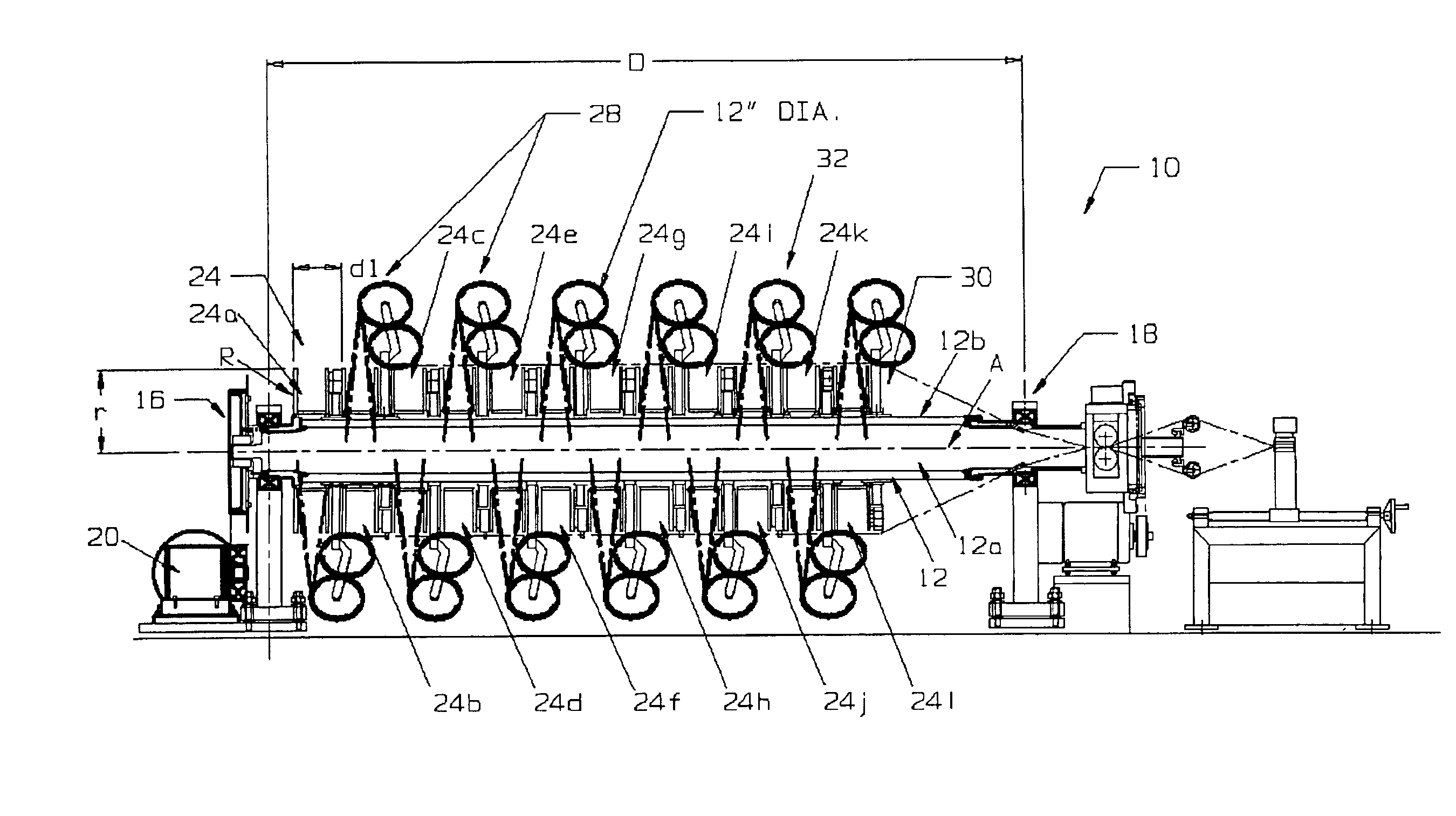
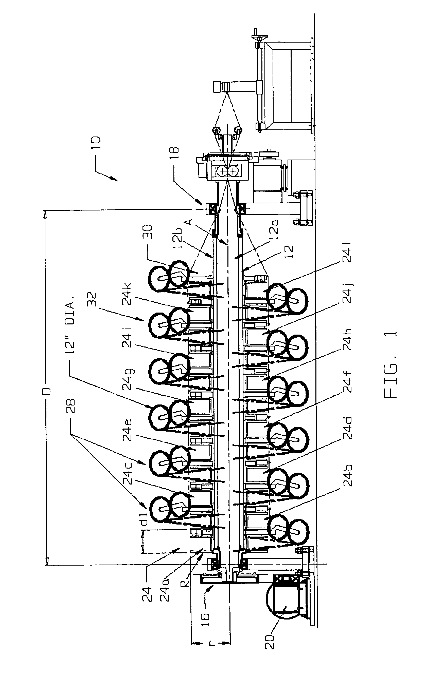
[0031]Referring now specifically to the Figures, in which identical or similar parts are designated by the same reference numerals throughout, and first referring to FIG. 1, a compact universal concentric strander in accordance with the present invention is generally designated by the reference numeral 10.

[0032]The concentric strander 10 includes a strander shaft 12 that has a concentric bore 12a and an exterior surface 12b. The strander shaft 12 defines a generally horizontal axis A and is rotatably mounted at its upstream and downstream ends 16, 18, respectively, on bearing supports, in a conventional manner. A drive motor 20 is provided to rotate the strander shaft 12 about the axis A.

[0033]As with the prior art central stranders, the strander 10 is provided with a plurality of bobbins 24 that are rotatably mounted on the strander shaft 12 and substantially uniformly spaced from each other along the shaft, as shown. In the embodiment illustrated, the concentric strander 10 includ...


PUM

PropertyMeasurementUnit
angleaaaaaaaaaa
enclosed angleaaaaaaaaaa

Abstract

A concentric strander has an elongate concentric shaft that defines a shaft axis and supports for rotatably supporting the concentric shaft. A number of wire bobbins are spaced at substantially equal intervals along the shaft to form spaces between the bobbins. Each bobbin has an axis substantially coextensive with the shaft axis for rotation about the shaft, and each bobbin has a maximum radial diameter. The strander has take-off sheaves, mounted on the shaft, that are associated with a wire bobbin and that take the wires from the bobbins and guide them to a point radially outwardly beyond the maximum predetermined radial bobbin diameter. The take-off sheaves subsequently guide the wires in a direction substantially parallel to the shaft axis and define, on rotation of the concentric shaft, a cylindrical envelope. At a downstream end of the shaft, the strander has a closing device that receives the wires from the bobbins and applies them on a core. A drive rotates the shaft, and the wire take-off sheaves are rotated by the interaction between the sheaves and the paid-off advancing wires. The interbobbin spaces needed to support the wire take-off sheaves have axial dimension substantially independent of the diameters of the wires to be processed by the strander.

Description

BACKGROUND OF THE INVENTION[0001]1. Field of the Invention[0002]This invention generally relates to wire and cable manufacturing machinery and, more specifically, to a concentric strander with take-off sheaves mounted on the strander and a method for assembling same.[0003]2. Description of the Prior Art[0004]Cables made of copper or aluminum conductor strands have been produced on a variety of machines, including rigid stranders, tubular stranders, double twist bunchers and planetary cage stranders. One strander design that has a number of advantages over the aforementioned machines is the concentric strander. Its advantages include high product quality resulting from constant wire pull, high quality wind, elimination of bobbins in favor of permanently installed product packages, high productivity, reliability and cost efficiency.[0005]Bobbins are supported on one proposed concentric strander on the strander shaft or rotor and arranged co-axially with a machine or strander axis so t...

Claims


Application Information

Patent Timeline
Patent Type & Authority Patents(United States)
IPC IPC(8): D07B3/00D07B3/04
CPCD07B3/045
Inventor BLACKMORE, ANDREWMARSHALL, MICHAEL
Owner ROTEQ MACHINERY
Why Eureka
Try Eureka