Process and circuit arrangement to monitor physical parameters

a technology of physical parameters and circuits, applied in the direction of transmission monitoring, testing circuits, instruments, etc., can solve the problems of not being able to establish how long a static ram memory can maintain a data template, difficult for the processor to differentiate whether the assembly is made, and difficult to distinguish between the three cases

Inactive Publication Date: 2005-09-20
WSOU INVESTMENTS LLC +1
View PDF6 Cites 4 Cited by
  • Summary
  • Abstract
  • Description
  • Claims
  • Application Information

AI Technical Summary

Benefits of technology

[0015]An important advantage to this improved circuit arrangement is seen in that the monitoring is done by at least two independent monitoring modules RG1, RG2, so that by suitably selecting the linking means V1 of the evaluation circuit A, improved results can be attained in comparison with a circuit arrangement with only one monitoring module. In particular, it is possible to test the at least two independent monitoring modules RG1, RG2 independent of one another. This has a significant advantage in comparison to known solutions, in that the monitoring modules RG1, RG2, can be tested without having to trigger a Reset of the entire digital assembly, inclusive of the test logic or diagnostic logic.
[0016]To this end, it is advantageous that the signals of the monitoring modules are linked by means of a logical AND function. This provides that only a state that is simultaneously established by the at least two monitoring modules RG1, RG2 can produce a valid Reset signal PON-RES for the digital assembly. However, an individual Reset signal by one of the monitoring modules as part of a test of this module does not trigger a Reset of the entire digital assembly.
[0018]According to an aspect of the invention, the circuit arrangement is suited advantageously for the monitoring of all physical parameters for which a Reset is required if a setpoint range is exceeded, for example for safety reasons or to prevent damage to the assembly, as well as to test the respective monitoring modules.
[0019]According to another aspect of the invention, for electronic assemblies, it is especially important to monitor electrical voltages, currents and temperatures. In the case of monitoring electrical voltages, this can prevent undefined logic states. If electrical currents and / or temperatures are monitored, damage caused by dissipation rates that are too high can be prevented by interrupting the current operation.
[0021]For clocked electronic logic assemblies that operate with high clock frequencies, it is required that stable clock states be attained before activating the logic circuitry. According to an aspect of the invention, Reset signals with their own individual time characteristics are provided through different output signal carrying means, making a delayed removal of the Reset signal for the logic circuitry compared with the removal of the Reset signal for the clock-generating circuit sections possible.
[0023]This process helps to make advantageous use of the circuit arrangement according to the invention to test the at least two independent monitoring modules RG1, RG2 independent of one another. This provides a significant advantage in comparison to known solutions in that the monitoring modules RG1, RG2 can be tested without having to trigger a Reset of the entire digital assembly inclusive of the test logic or diagnostic logic.

Problems solved by technology

However, since this test triggers the same Power-On Reset as is triggered when the device is turned on or during a strong fluctuation in the power supply voltage, it is very difficult for the processor to differentiate whether the assembly has just been turned on, a “true” Power-On Reset, or whether a test of the voltage monitoring module, a “simulated” Power-On Reset, was responsible for the Power-On Reset.
However, the differentiation of these three cases is not clear-cut all the time, due to physical effects, for example.
For example, it has not been established how long a static RAM memory can maintain a data template without an operating voltage.
Also, cases in which the “test data template” has just been written into the memory register and the Reset is triggered not by the test signal, but by a random voltage fluctuation, cannot be differentiated from cases in which the Reset is triggered by the test signal.

Method used


Image

  • Process and circuit arrangement to monitor physical parameters
  • Process and circuit arrangement to monitor physical parameters
  • Process and circuit arrangement to monitor physical parameters

Examples


Embodiment Construction

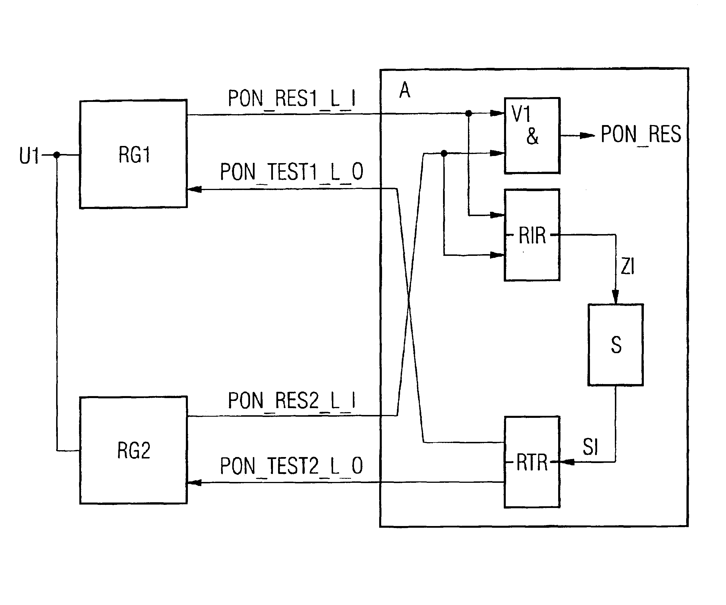
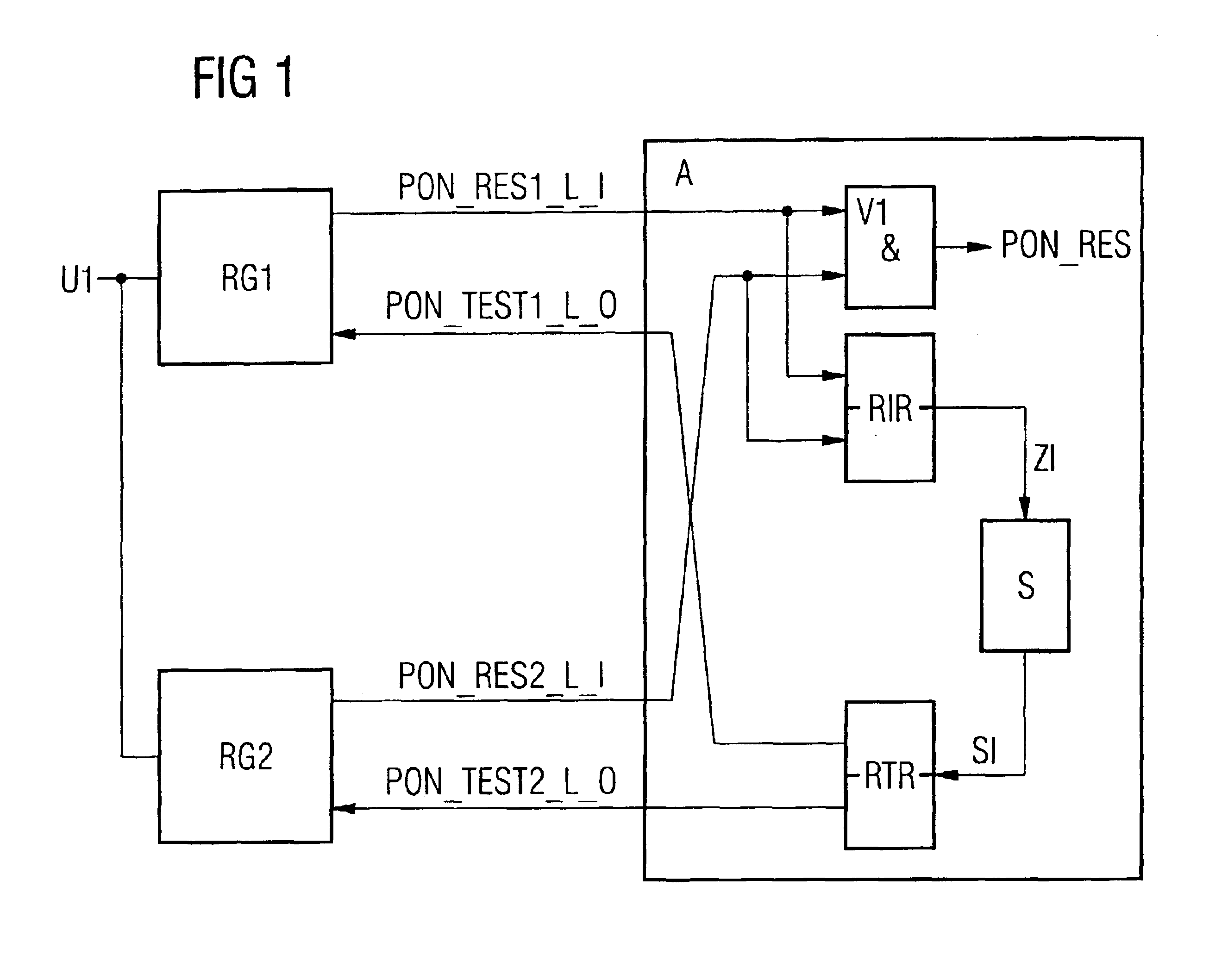
[0026]FIG. 1 shows an electrical voltage U1, which is monitored by a first Power-On Reset generator RG1 (called voltage monitoring module RG1 below) and a second Power-On Reset generator RG2 (called voltage monitoring module RG2 below). When the voltage U1 deviates from a prescribed setpoint range, for example a nominal value of 5 volts with an allowable deviation of ±5% of the nominal value, the first voltage monitoring module RG1 produces a Reset signal on a first Reset line PON_RES1_L_I (Power-On_Reset1_Low-active_Input) that is an output line of the first voltage monitoring module RG1, and the second voltage monitoring module RG2 produces a Reset signal on a second Reset line PON_RES2_L_I (Power-On Reset2_Low-active_Input) that is an output line of the second voltage monitoring module RG2.

[0027]The first voltage monitoring module RG1 has an input line PON_TEST1_L_O (Power-On_Test1_Low-active_Output), through which a first test signal can be input to the first voltage monitoring ...


PUM


Abstract

Monitoring is performed by at least two independent monitoring modules whose signals are linked through linking means. This makes it possible to test the two independent monitoring modules independent of one another.

Description

CLAIM FOR PRIORITY[0001]This application claims priority to Europe Application No. 02000813.2 which was filed in the German language on Jan. 14, 2002.TECHNICAL FIELD OF THE INVENTION[0002]This invention pertains to a circuit arrangement and process to monitor physical parameters as well as a process to diagnose the circuit arrangement according to the invention, in particular for use in telecommunications equipment.BACKGROUND OF THE INVENTION[0003]In digital assemblies, the power supply voltage is monitored through a voltage monitoring module. If the deviation of the power supply voltage from its setpoint reaches or exceeds a specified threshold value, the voltage monitoring module triggers a reset of the entire digital assembly, called a “Power-On Reset” below, so as to prevent any undefined logic states. Likewise, the entire digital assembly is provided with a Power-On Reset signal during the time the power supply voltage is turned on, which has the effect of keeping the digital a...

Claims


Application Information

Patent Timeline
Patent Type & Authority Patents(United States)
IPC IPC(8): G01R19/165H04B17/00
CPCG01R19/16538H04B17/0085H04B17/309
Inventor SEITZ, HANS-JUERGEN
Owner WSOU INVESTMENTS LLC
Why Eureka
Try Eureka