Device and method for transmitting light over an optical fiber

Inactive Publication Date: 2005-09-20
INSTR SYST
View PDF9 Cites 226 Cited by
  • Summary
  • Abstract
  • Description
  • Claims
  • Application Information

AI Technical Summary

Benefits of technology

[0017]The advantage of the invention consists in that changes in the fiber transmission due to changes in position of the thick core fiber may be effectively suppressed in a relatively compact construction of the device as follows: Usually, when the light is coupled in an optical fiber, not all transmission modes are excited. This means that the beam profile is non-homogenous at the output end of the optical fiber, and may also be further altered if the optical fiber is moved. In particular, however, a non-homogenous beam profile leads to measurement errors in such optical measuring devices, which by virtue of their function must attenuate a portion of the beam profile (e.g. a grid spectrometer with its specific input aperture). To alleviate this situation, the mode mixer (the curved rigid subsegment) has been added, the curvature of which falls below a first threshold value. Of course, this threshold value for fiber curvature is determined by the material used, the diameter and length of the thick core fiber, the overall configuration of the optical apparatus (particularly the input coupling of the light beam in the thick core fiber) and the required degree of mode mixing / homogenization.
[0018]However, since the homogenization of the light bundle may be measured easily, the threshold value may also be determined experimentally with reference to the parameters indicated (i.e., the actual measurement construction), and the curved guide may be shaped accordingly.
[0019]Regarding this threshold value for the purposes of the use according to the invention of thick core fibers as optical fibers, the following should also be noted: in much of the literature containing notes on the use of thick core fibers, it is recommended that the minimum radius of curvature must not be less than 300× the diameter of the fiber. This means, for example, that a thick core fiber having a diameter of 600 micrometers must have a radius of curvature of at least 18 cm, which is not adequate for mode mixing (see below). However, it has been determined that considerably smaller radii of curvature can be achieved with these thick core fibers. The limits recommended by the manufacturers appear to have their origin in the fact that most such thick core fibers are produced for transmitting high luminous power for materials processing. With small radii of curvature, a portion of the light escapes from the fiber, a further portion is converted to cladding modes (see below). The result of both is that the fiber is destroyed at high luminous powers due to high light absorption. However, luminous power transmitted in measurement equipment is lower, with the result that the fibers cannot be destroyed, even with radii of curvature of as small as those indicated.
[0020]It should be noted further that for the most extensive mode mixing (i.e., excitation of practically all transverse modes) the emergence angle of the light from the thick core fibers also assumes the constant value for the digital aperture, and the effect on the emergence angle of changing the position of the thick core fibers is at most negligible.
[0021]This is desirable for the stability of the measurement signal and in applications involving a spectrometer.
[0022]The angle of emergence and the intensity distribution of the light exiting thick core fibers can also be measured easily, for example by directing the exiting light against a surface arranged perpendicularly to the thick core fiber and examining the shape of the beam spot projected thereonto. In this way, for example, the first threshold value can be determined by testing the angle of curvature for which the size of the projected beam spot is greatest. This does not necessarily mean that all modes are also excited. However, in this case it may be assumed that the light beam profile is extensively homogenized.

Problems solved by technology

However, this has the fundamental disadvantage that sophisticated optical mirrors must be used to guide the beam due to the linear scatter of the free beam.
Moreover, additional difficulties arise, for example, if the input optic has to be moved, perhaps to provide a grid scan of a display surface that is to be measured in position offset luminance studies.
To protect the glass fibers from the unforgiving environmental conditions in industrial installations, they are usually installed unsecured in impact-resistant protective conduits.
However, transmission of the light between two optical components by means of a glass fiber suffers from a serious drawback in that both the transmission of the light through the glass fiber and the spatial and angular distribution of the light at the source depend on the position (or course) of the glass fiber.
It may be seen, therefore, that the use of glass fibers particularly for transmitting a measured light signal from a mobile optical component to a fixed optical component causes significant disturbance to the measured light signal.

Method used


Image

  • Device and method for transmitting light over an optical fiber
  • Device and method for transmitting light over an optical fiber
  • Device and method for transmitting light over an optical fiber

Examples


first embodiment

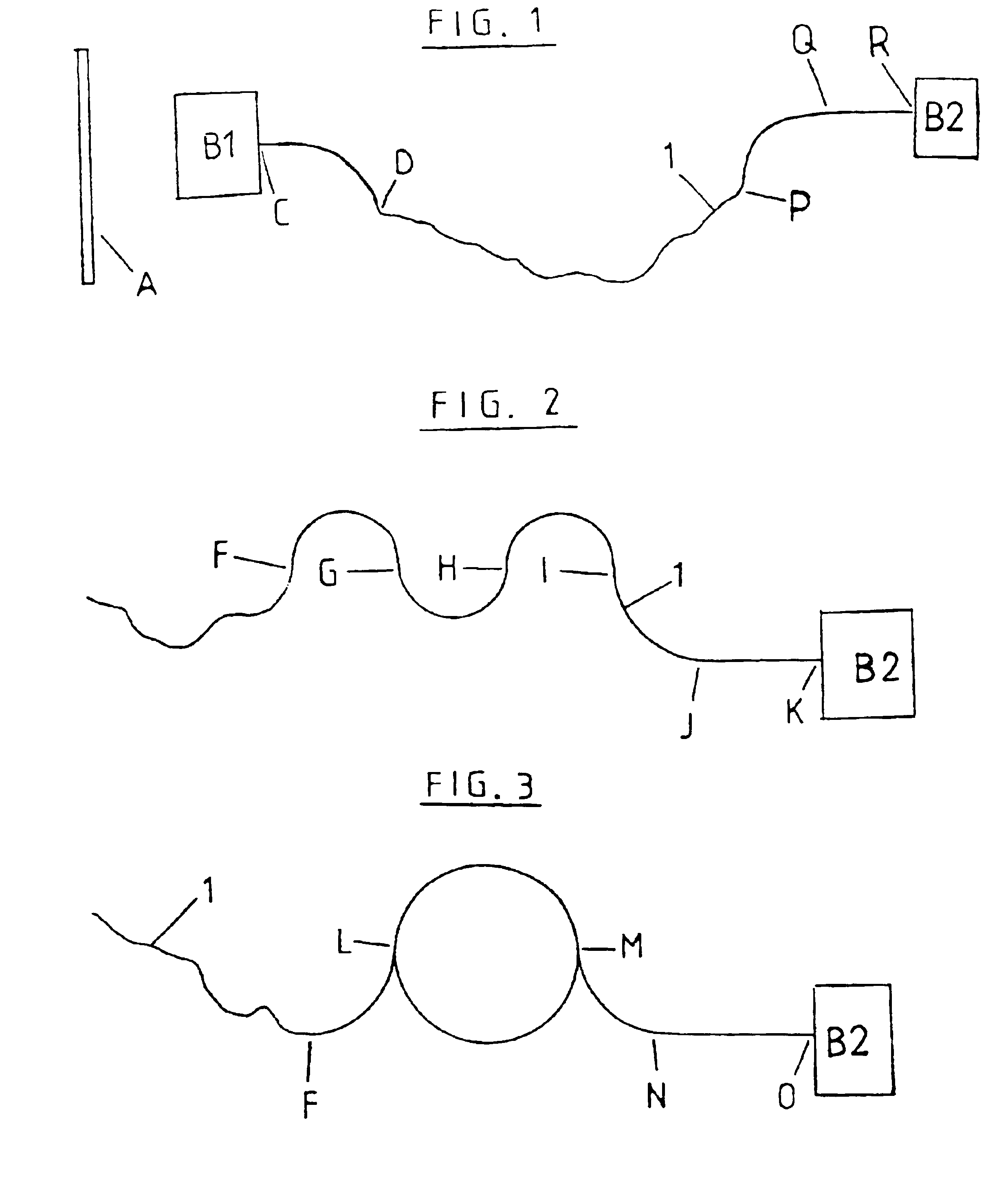
[0049]FIG. 1 shows a first embodiment for attachment of a reinforcing means in combination with a guidance means according to a first configuration for rigid or curved guidance of subsegments of a thick core fiber 1 in fiber output region, and a reinforcing means for rigid guidance of a further subsegment of thick core fiber 1 in the fiber input region. The light from the object or process A to be measured is coupled into thick core fiber 1 via an input optic B1. For this purpose, immediately upon exiting input optic B1, thick core fiber 1 is rigidly guided by a reinforcing means (not shown in detail) from input optic B for a specific length between points C and D. This reinforcing means is used to secure the fiber end at the input side, so that movement of thick core fiber 1 does not cause canting of the fiber end at the input side. This reinforcement means may guide the fibers in any geometry as required, (preferably at a 45° angle or also in a straight line), its guidance length ...

second embodiment

[0057]FIG. 2 shows the arrangement of a reinforcing means and a guidance means according to a second configuration for curved, rigid guidance of at least a subsegment of a thick core fiber 1 in the fiber output area. The light is supplied to thick core fiber 1 by an optical component (e.g. the input optic B1 of FIG. 1 according to the course of thick core fiber 1 as illustrated in FIG. 1) not shown in FIG. 2. As far as point F, thick core fiber 1 may be guided, for example, unsecured and flexibly arranged inside an impact-resistant guide conduit—not further shown. Between points F and I, thick core fiber 1 is then guided rigidly inside the guidance means according to the second configuration, which is conformed so that thick core fiber 1 extends in a “w” formation within the second guidance means. Because of its “w” shaped formation, the thick core fiber within the second guidance means passes through a reversal point at least at points G and H (in FIG. 2 still at points F and I), a...

third embodiment

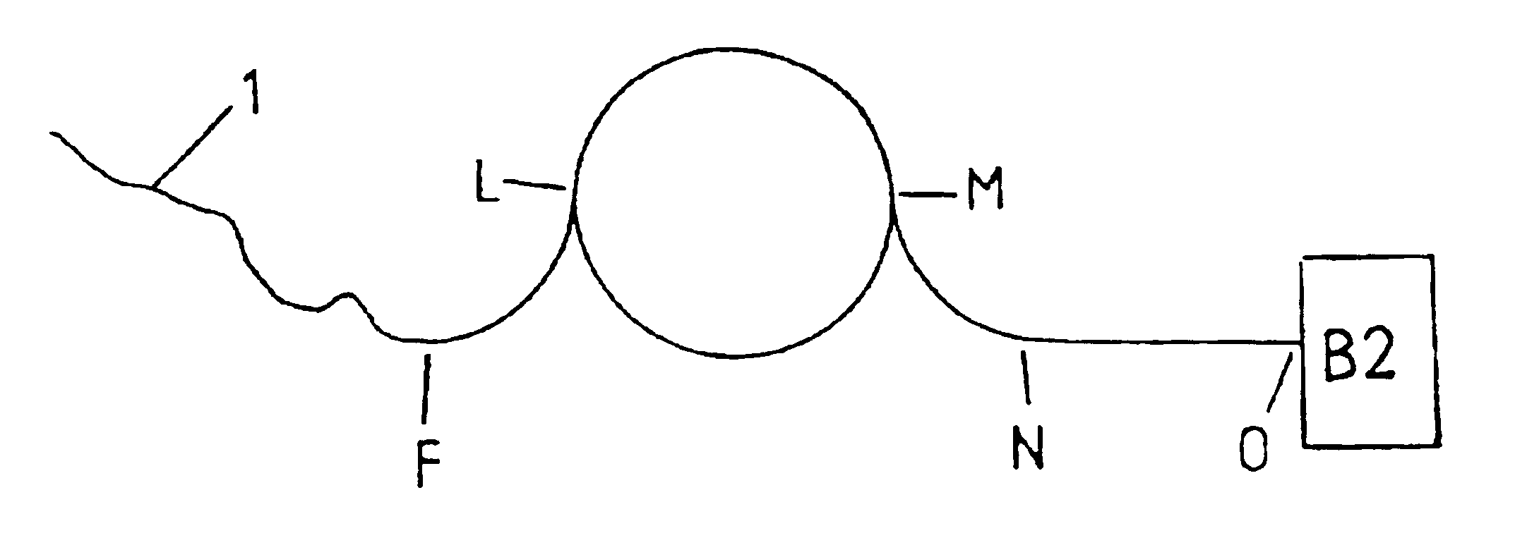
[0059]FIG. 3 shows an arrangement of reinforcing means and a guidance means according to a third configuration for guiding at least a subsegment of a thick core fiber 1 in curved manner at the fiber output end. As before, thick core fiber 1 is guided, for example, unsecured in an impact-resistant protective conduit as far as point F, between point F and point L it is rigidly guided in an arc segment having an angle of curvature of 90° of the guidance means according to the third configuration (radius of curvature smaller than the first threshold value), from point L to point M in a section of the guidance means in which the thick core fiber is rigidly guided around one and a half complete revolutions (radius of curvature smaller than the first threshold value), from point M to point N again in an arc segment having an angle of curvature of 90° of the guidance means according to the third configuration (radius of curvature smaller than the first threshold value) and from point N to a...


PUM


Abstract

The invention relates to a method and device for transmitting light over a fat fiber (1) between optical components (B1; B2) of an optical measuring device, which are provided at a launching end (C) and at an extraction end (R; K; O) of the fat fiber (1). Said measuring device comprises a guiding means for the curved rigid guidance of a first partial section (PQ; FGHI; IJ; FL; LM; MN) of the fat fiber (1). If the radius of curvature of the curved guidance falls below a first limit, the light beam profile of the fat fiber (1) is homogenized by a mode mixing. In order to diminish the effect on the transmitted light caused by a permitted change in position of the fat fiber (1), a stiffening means, which is rigidly connected to the guiding means, is provided for rigidly guiding a second partial section (QR; JK; NO) of the fat fiber (1). Said second partial section connects to the first partial section (PQ; FGH; IJ; FL; LM; MN) and extends essentially up to the optical component (B2) located at the extraction end (R; K; O), whereby the entire length of the first and second partial section is at least provided with a length that renders the extraction end (R; K; O) of the fat fiber (1) mechanically stable.

Description

CROSS-REFERENCE TO OTHER APPLICATIONS[0001]This Application is a National Phase of International Application No. PCT / EP01 / 05037, filed on May 4, 2001, which claims priority from German Patent Application No. 100 21 940.3, filed on May 5, 2000.BACKGROUND TO THE INVENTION[0002]The invention relates to a device and a method for transmitting light fiber in accordance with the pre-characterizing clauses of claims 1, 20 and 25.SUMMARY OF THE INVENTION[0003]One exemplary configuration relates to the measurement of photometric or radiometric values, in which the light is transmitted between the input optic (first optical component) and a suitable measuring instrument (second optical component) via a glass fiber (waveguide or optical fiber). Glass fiber transmission has the advantage that both optical components (in this case the input optic and the measuring instrument) may be located at a distance from one another, particularly if one of the two optical components (in this case the measur...

Claims


Application Information

Patent Timeline
IPC IPC(8): G02B6/36G02B6/28G02B6/42G02B6/38G02B6/14
CPCG02B6/2808G02B6/3887G02B6/4204G02B6/14G02B6/4478
Inventor KOHNS, PETER
Owner INSTR SYST
Why Eureka
Try Eureka