
Seal for coaxial cable in downhole tools

a technology of coaxial cable and downhole tool, which is applied in the direction of connection contact material, coupling device connection, drilling pipe, etc., and can solve the problems of overall failure, reducing the probability of bit error,

Active Publication Date: 2005-09-20
INTELLISERV LLC
View PDF117 Cites 146 Cited by
  • Summary
  • Abstract
  • Description
  • Claims
  • Application Information

AI Technical Summary

Benefits of technology

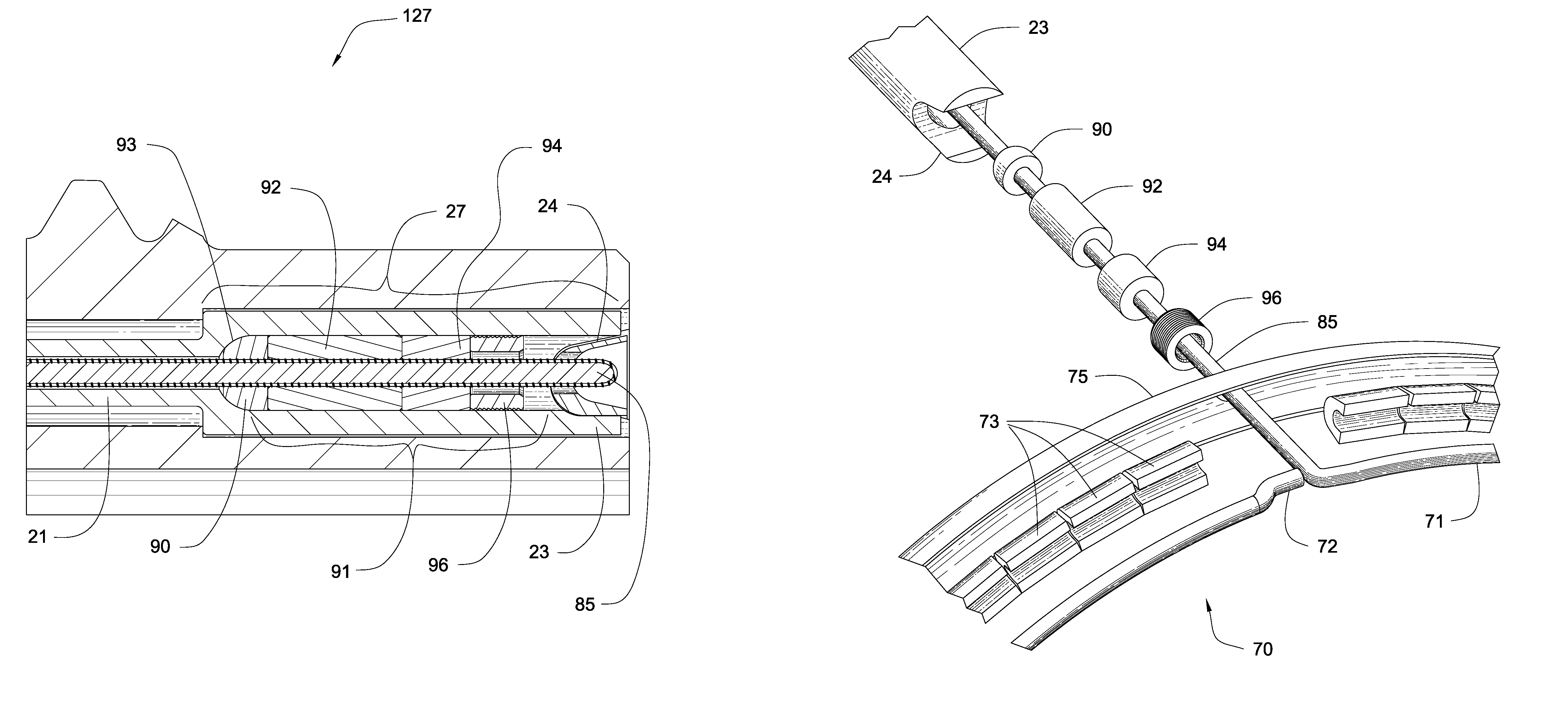
[0010]An object of this invention is to provide for a reliable seal for a coaxial electrical connection between an electrical transmission line and a communications element. For example a coaxial cable disposed within a downhole tool, such as a drill pipe, and an inductive transformer housed within a tool joint end of the drill pipe. Downhole information collected at the bottom of the borehole and other locations along the drill string is then sent up through the data transmission system along the drill string to the drilling rig in order to be analyzed. A data transmission system utilizing such an electrical connector with its attendant seal can perform with increased robustness and has the further advantage of being coaxial.
[0011]Data received along the drill string employing such a data transmission system will decrease the likelihood of bit errors and overall failure. In this manner, information on the subterranean conditions encountered during drilling and on the condition of the drill bit and other downhole tools may be communicated to the technicians located on the drilling platform. Furthermore, technicians on the surface may communicate directions to the drill bit and other downhole devices in response to the information received from the sensors, or in accordance with the predetermined parameters for drilling the well.

Problems solved by technology

Data received along the drill string employing such a data transmission system will decrease the likelihood of bit errors and overall failure.

Method used


Image

  • Seal for coaxial cable in downhole tools
  • Seal for coaxial cable in downhole tools
  • Seal for coaxial cable in downhole tools

Examples


Embodiment Construction

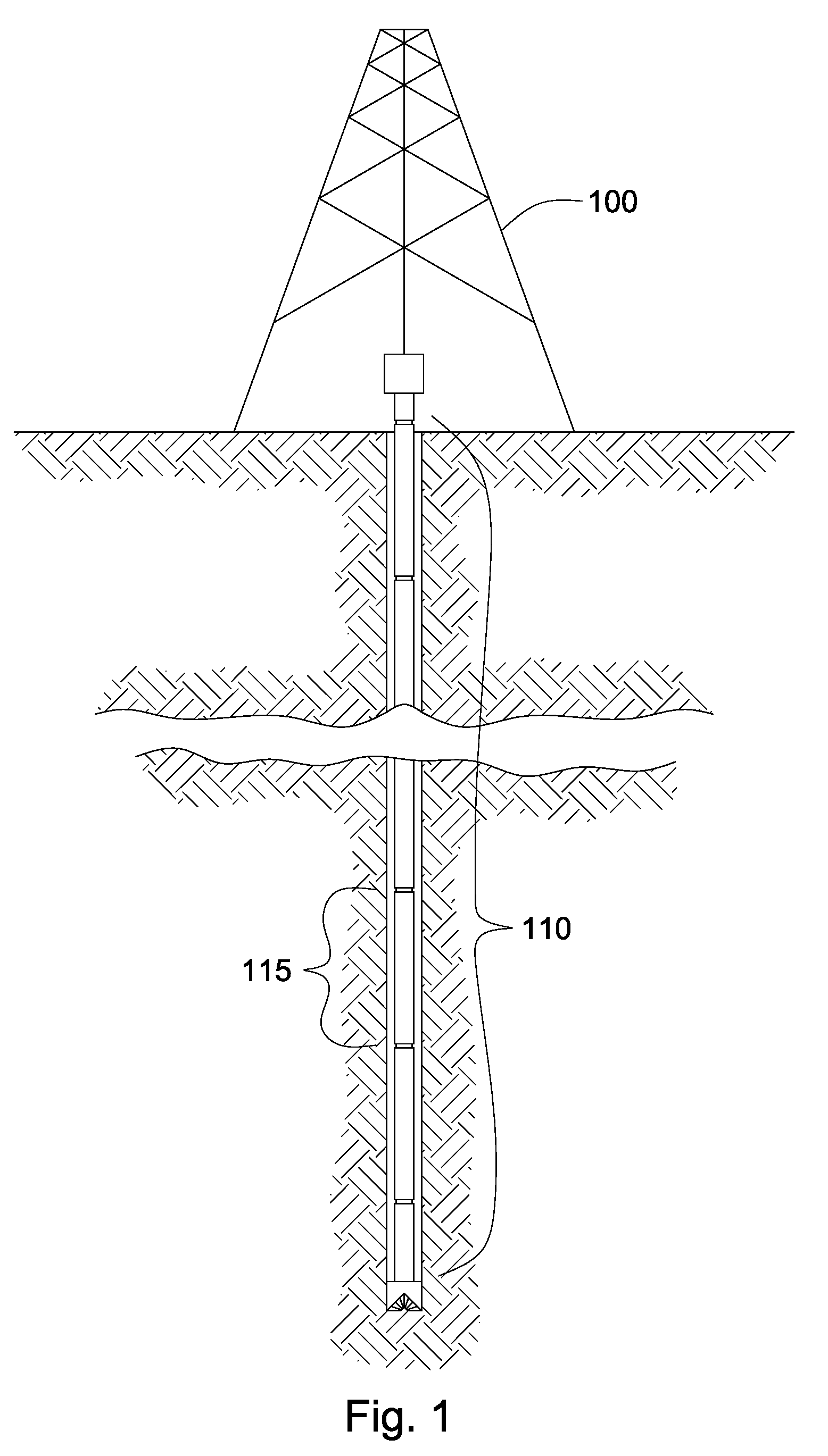
[0037]Referring to the drawings, FIG. 1 is a schematic representation of a drill string 110 in a borehole as used on a drilling rig 100 including drilling tools 115. Some examples of drilling tools are drill collars, jars, heavy weight drill pipe, drill bits, and of course drill pipe.

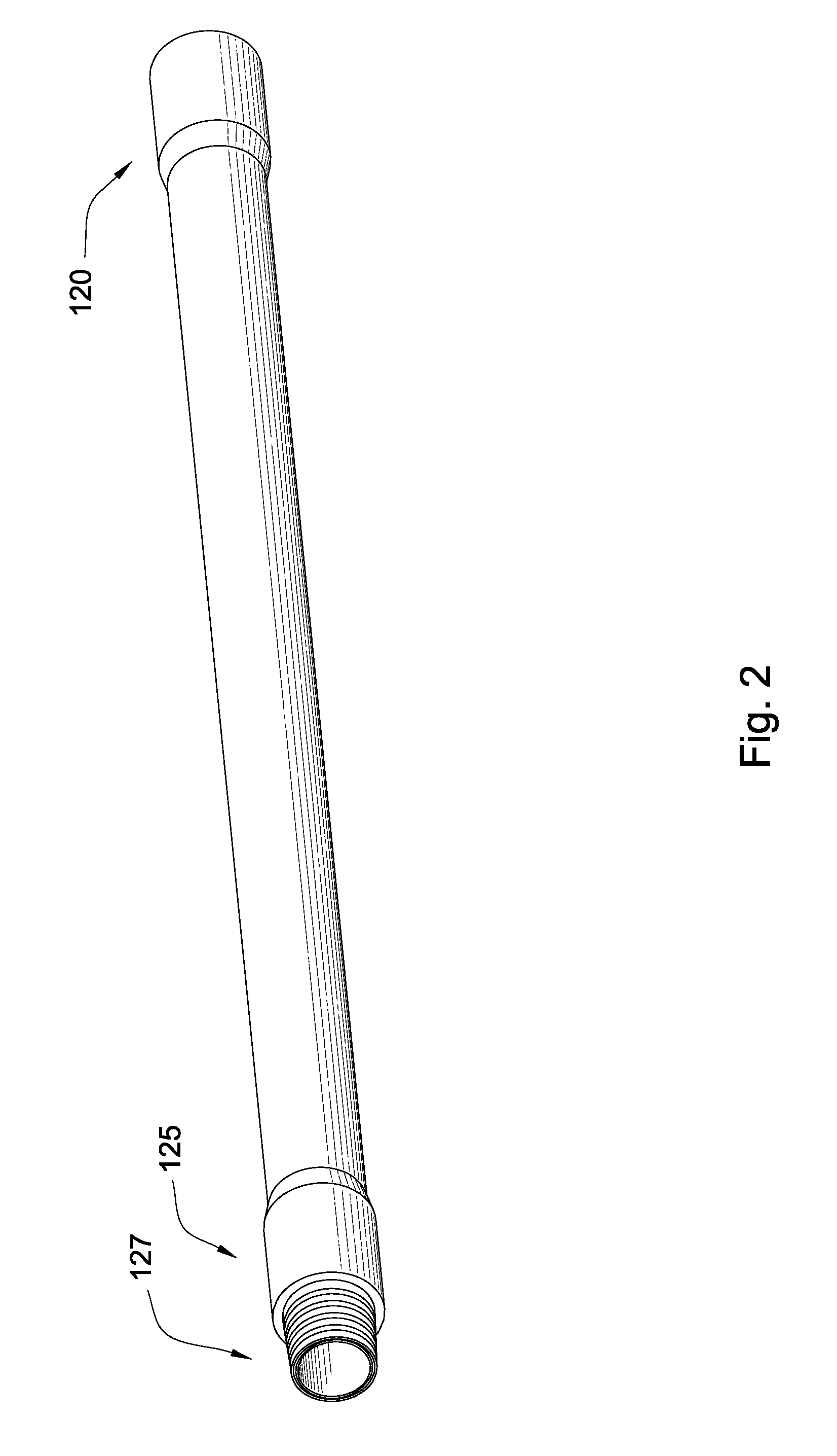
[0038]FIG. 2 shows one example of a drilling tool, a drill pipe 115 including a box end tool joint 120, pin end tool joint 125, and the pin nose 127 of pin end tool joint 125. Tool joints are attached to the tool and provide threads or other devices for attaching the tools together, and to allow a high torque to be applied to resist the forces present when making up a drill string or during drilling. Between the pin end 125 and box end 120 is the body of the drill pipe section. A typical length of the body is between 30 and 90 feet. Drill strings in oil and gas production can extend as long as 20,000 feet, which means that as many as 700 sections of drill pipe and downhole tools can be used in the drill...


PUM


Abstract

A seal for a coaxial cable electrical connector more specifically an internal seal for a coaxial cable connector placed within a coaxial cable and its constituent components. A coaxial cable connector is in electrical communcation with an inductive transformer and a coaxial cable. The connector is in electrical communication with the outer housing of the inductive transformer. A generally coaxial center conductor, a portion of which could be the coil in the inductive transformer, passes through the connector, is electrically insulated from the connector, and is in electrical communication with the conductive core of the coaxial cable. The electrically insulating material also doubles as a seal to safegaurd against penetration of fluid, thus protecting against shorting out of the electrical connection. The seal is a multi-component seal, which is pre-compressed to a desired pressure rating. The coaxial cable and inductive transformer are disposed within downhole tools to transmit electrical signals between downhole tools within a drill string. The internal coaxial cable connector and its attendant seal can be used in a plurality of downhole tools, such as sections of pipe in a drill string, drill collars, heavy weight drill pipe, and jars.

Description

FEDERAL RESEARCH STATEMENT[0001]This invention was made with government support under Contract No. DE-FC26-01NT41229 awarded by the U.S. Department of Energy. The government has certain rights in the invention.BACKGROUND OF INVENTION[0002]The present invention relates to the field of electrical connectors, particularly seals for electrical connectors for coaxial cables. The preferred electrical connectors are particularly well suited for use in difficult environments wherein it is desirable to electrically connect inside a coaxial cable without the normal means available such as BNC, RCA, SMA, SMB, and TNC type coaxial connectors. The preferred seals for electrical connectors are particularly well suited for use in difficult environments wherein it is desirable to seal inside a coaxial cable without the normal means available such as o-rings in machined grooves, metal o-rings, or a split metallic ring. One such application is in data transmission systems suitable for downhole enviro...

Claims


Application Information

Patent Timeline
Patent Type & Authority Patents(United States)
IPC IPC(8): E21B17/00E21B17/02H01R13/533H01R13/52
CPCE21B17/003E21B17/028H01R13/533H01R13/521
Inventor HALLHALL, JR., H. TRACYPIXTON, DAVID S.DAHLGREN, SCOTTFOX, JOESNEDDON, CAMERONBRISCOE, MICHAEL
Owner INTELLISERV LLC
Learn More