
Method and system for transmitting data between a receiver and a transmitter

a technology of transmitting data and receiver, applied in the field of method and system for transmitting data between a receiver and a transmitter, can solve the problems of delay and waste of bandwidth, and the transmitter does not necessarily know if, so as to achieve reliable transmission and efficient use of bandwidth.

Inactive Publication Date: 2005-09-13
HEWLETT PACKARD DEV CO LP
View PDF20 Cites 49 Cited by
  • Summary
  • Abstract
  • Description
  • Claims
  • Application Information

AI Technical Summary

Benefits of technology

[0007]Another object of the present invention is to provide an improved method and system for allowing a transmitter to send a data packet to a receiver only after the receiver has resources to receive the packet.
[0008]Still another object of the present invention is to provide an improved method and system for transmitting data via at least one high-speed link with a plurality of virtual channels using more efficient bandwidth.
[0010]The present invention provides a method and a system for transmitting data between one or more receivers operatively connected to one or more transmitters, and more particularly to a method and a system for permissible transmission via at least one high-speed link having a plurality of virtual channels. By having the receiver send a credit packet with a unique virtual channel number that is specifically assigned to each virtual channel only when it has a buffer available, the present invention is able to bypass the need for an acknowledgement packet, resulting in reliable transmissions and efficient use of bandwidth.

Problems solved by technology

The problem with using acknowledgement packets is that the transmitter does not necessarily know if the receiver is ready to receive a packet in the first place.
As a result, it must rely on some timer to know when to try again, causing delay and waste of bandwidth.
Again, this causes both delay and waste of bandwidth by blocking other virtual channels.

Method used


Image

  • Method and system for transmitting data between a receiver and a transmitter
  • Method and system for transmitting data between a receiver and a transmitter
  • Method and system for transmitting data between a receiver and a transmitter

Examples


Embodiment Construction

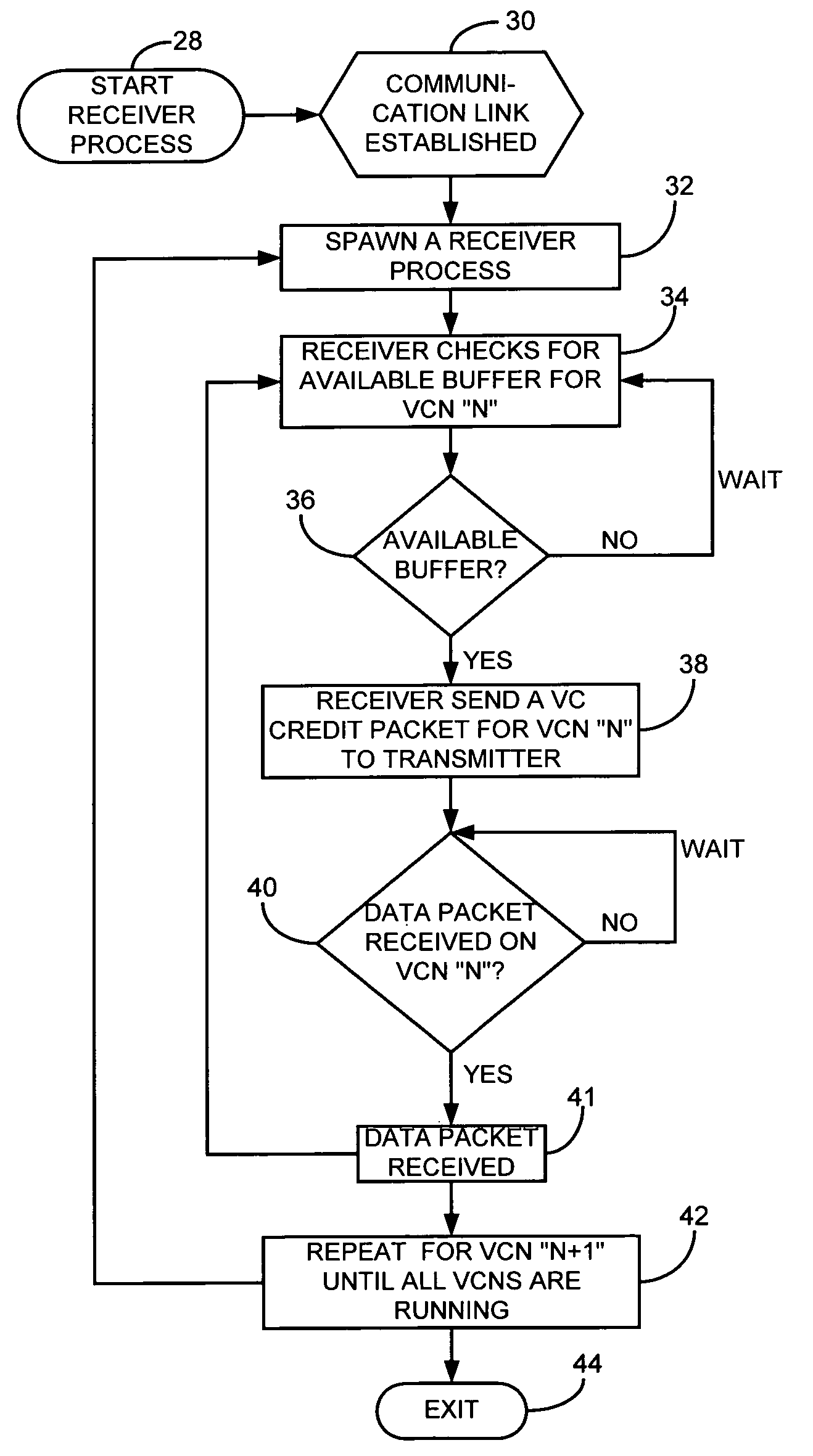
[0018]Broadly stated, the present invention is directed to a method and a system for transmitting data between at least one receiver operatively connected to at least one transmitter over a high-speed link with a plurality of virtual channels. Each virtual channel is assigned with a unique virtual channel number. When the receiver is ready for transmission for a particular virtual channel, it sends a virtual channel credit packet bearing the assigned virtual channel number. The transmitter then responds to the virtual channel credit packet. After the transmission for this particular virtual channel is finished, the process is repeated for the next virtual channel until all the virtual channels are running.

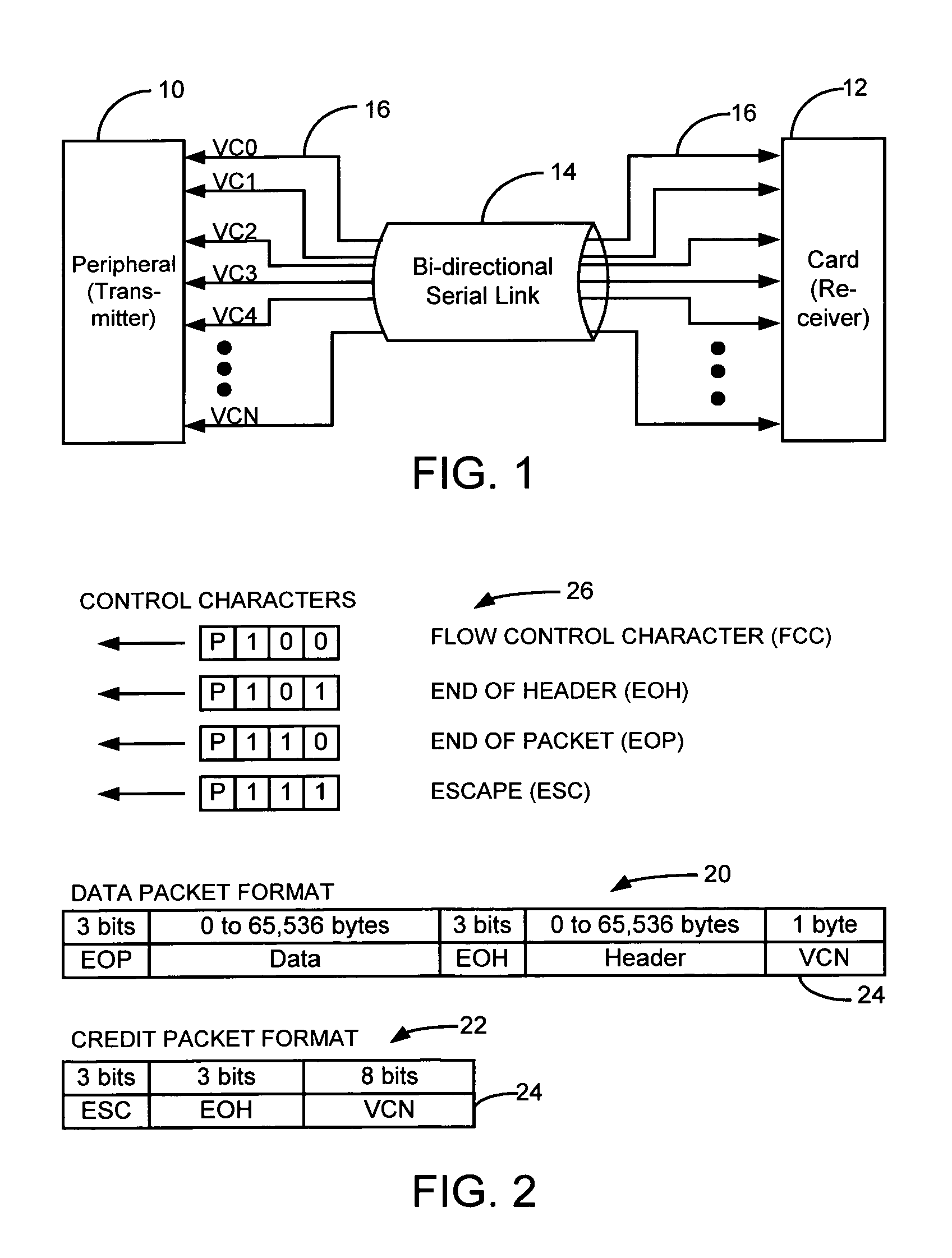
[0019]Turning now to FIG. 1, a schematic diagram of an exemplary connection between a peripheral device or peripheral and an I / O card is shown and illustrates one way in which the receiver is connected to the transmitter for the implementation of the present invention. However, it ...


PUM


Abstract

A method and system for transmitting data between at least one receiver operatively connected to at least one transmitter, and more particularly to a method and a system for permissible transmission via at least one high-speed link having a plurality of virtual channels. The method includes the receiver sending a virtual channel credit packet for a particular virtual channel to the transmitter, the credit packet being indicative that the receiver is available to receive data and having a unique virtual channel number assigned to said particular virtual channel thereto. The transmitter responds to the virtual channel credit packet, which includes transmitting data to the receiver if data is available. The receiver receives the data transmitted from the transmitter.

Description

[0001]The present invention generally relates to a method and a system for transmitting data between at least one receiver operatively connected to at least one transmitter, and more particularly to a method and a system for permissible transmission via at least one high-speed link having a plurality of virtual channels.[0002]Virtual channels are generally used for maximum efficiency usage of a single bi-directional serial link between a receiver and a transmitter. The communication is usually based on asynchronous concurrent processes at the packet level. More specifically, Communicating Sequential Processes (“CSP”) is used for synchronized communication between the receiver and transmitter, meaning each communicating process waits until data transfer is complete before continuing.[0003]One known method for maintaining the CSP while ensuring that no data is lost or overwritten suggests the use of acknowledgement packets. The receiver must acknowledge each packet before another can ...

Claims


Application Information

Patent Timeline
IPC IPC(8): H04L12/56H04Q11/04
CPCH04L47/10H04L47/16H04L47/39H04Q11/0478H04L2012/563
Inventor JONES, SCOTT ARTHURBERKEMA, ALAN CHRISLE, THANG VINHANAST, FRED JOEL
Owner HEWLETT PACKARD DEV CO LP
Learn More