
Method, system, and software for signal processing using pyramidal decomposition

Active Publication Date: 2005-09-13
INTELLECTUAL VENTURES ASSETS 20
View PDF160 Cites 13 Cited by
  • Summary
  • Abstract
  • Description
  • Claims
  • Application Information

AI Technical Summary

Benefits of technology

[0011]An advantage of at least one embodiment of the present invention is that unwanted noise in a signal is reduced without reducing the desired portion of the signal.
[0012]An additional advantage of at least one embodiment of the present invention is that signal quality is improved for a desired signal component without degrading a other desired signal components.
[0013]Yet another advantage of at least one embodiment of the present invention is that calculations to improve signal quality can be performed relatively quickly, due to a lower processing overhead and less user intervention than conventional methods.

Problems solved by technology

However, conventional methods used to reduce noise are ineffective or slow.
In some methods, the level of noise reduction is unsatisfactory.
In other methods, the reduction of noise is destructive and removes a significant amount of desired information from the signal.
In addition, many of these methods require an excessive amount of processing time to perform, tying up processing resources.
However, the use of blurring on the base image often causes a degradation of detail, as the edges are blurred.
To prevent a significant loss of detail, conventional image noise reduction methods reduce the level of noise reduction, thereby diminishing the effectiveness of the blurring process.
The conventional blurring methods can also require relatively extensive processing as the base image is processed at the base resolution.
Given the drawbacks in current noise reduction methods, it is clear that conventional methods are less than perfect.

Method used


Image

  • Method, system, and software for signal processing using pyramidal decomposition
  • Method, system, and software for signal processing using pyramidal decomposition
  • Method, system, and software for signal processing using pyramidal decomposition

Examples


Embodiment Construction

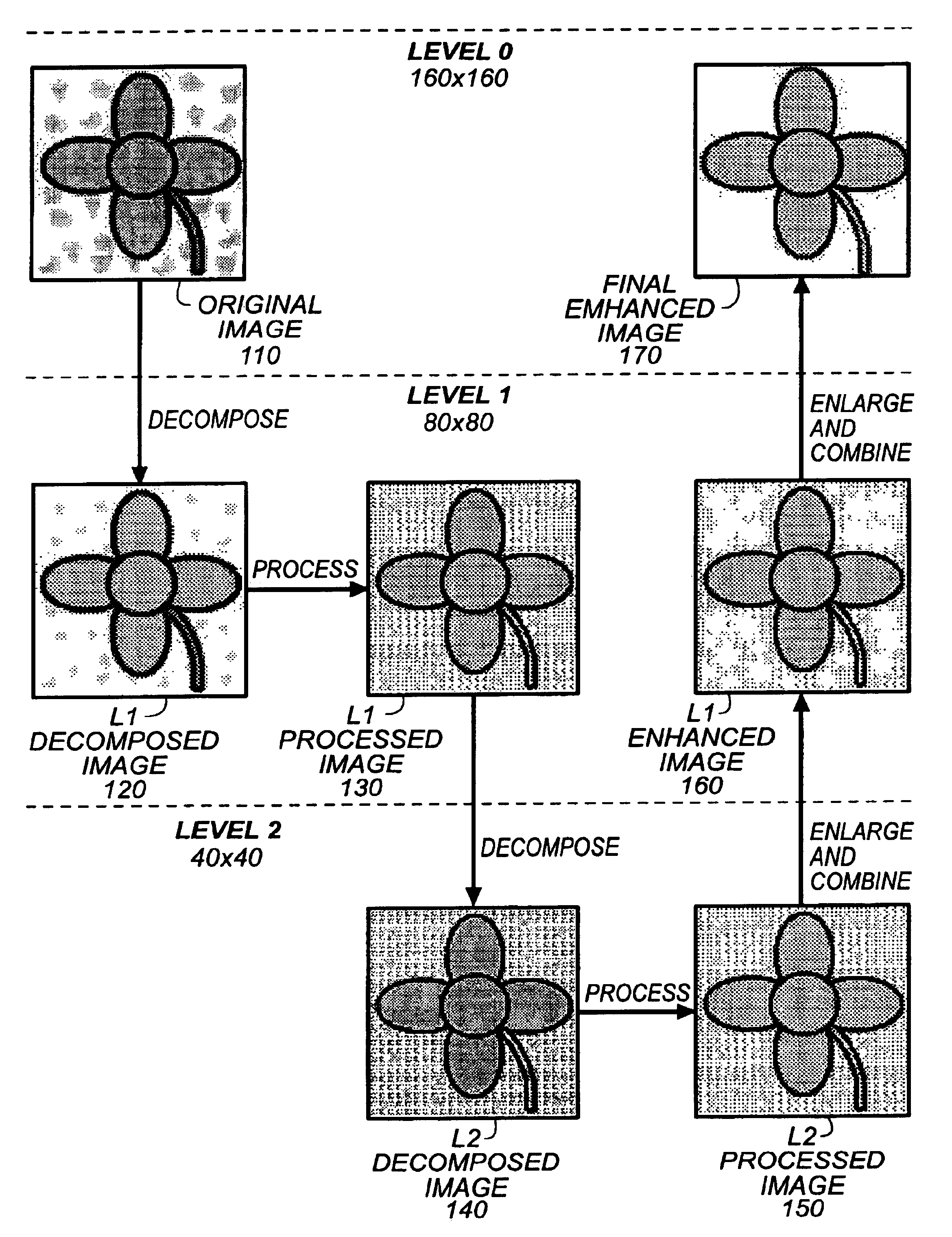
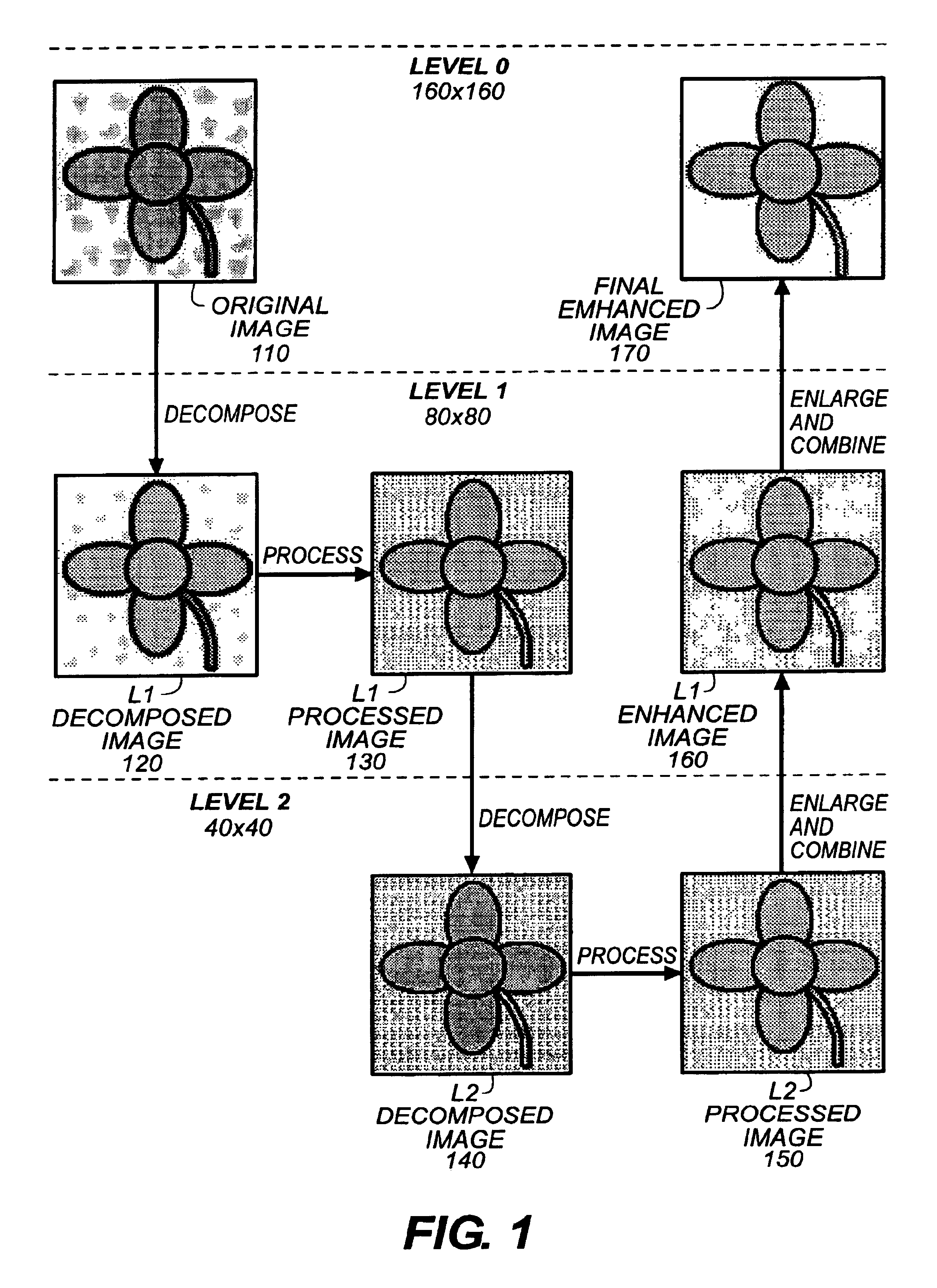
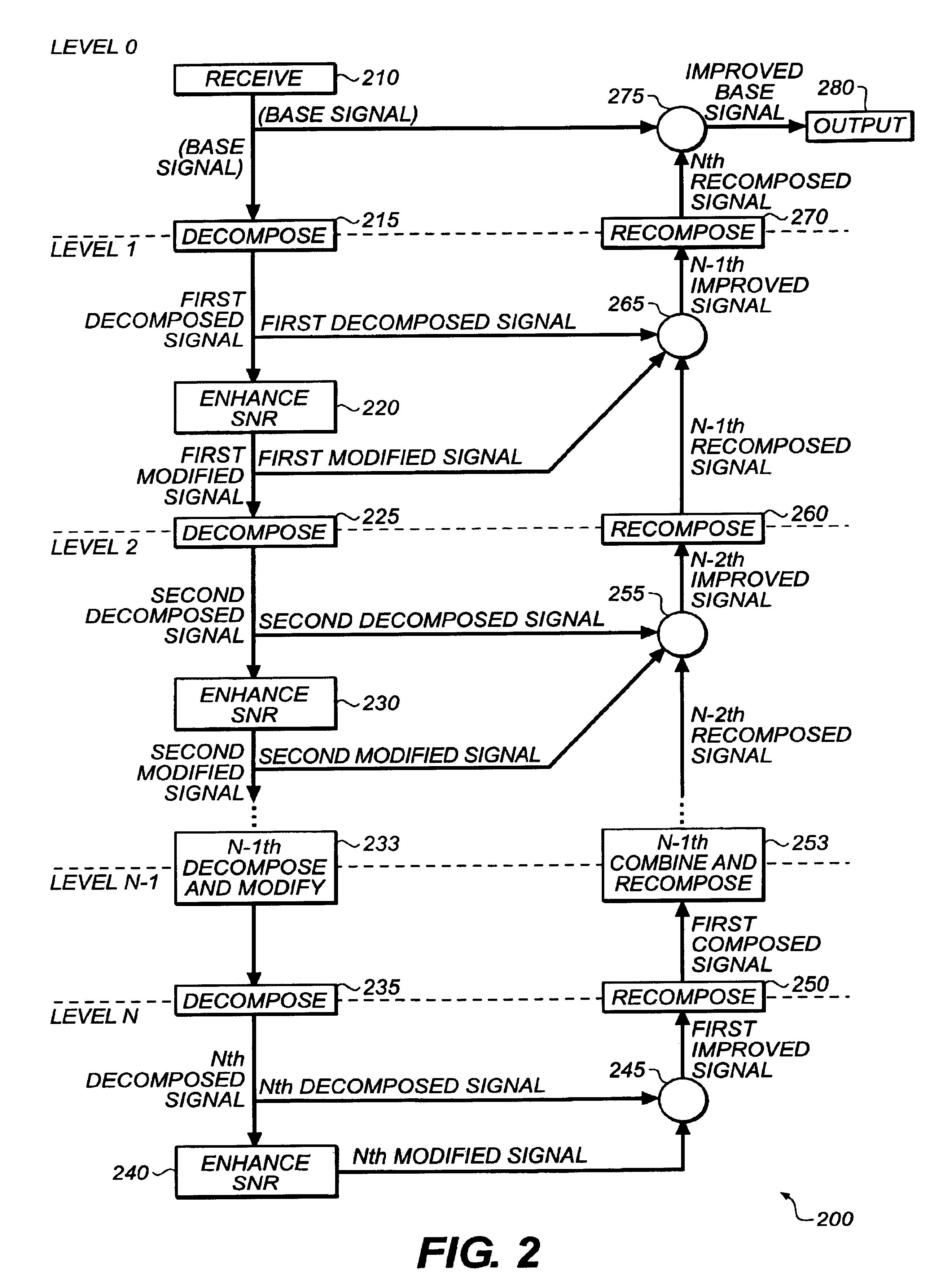
[0026]FIGS. 1-16 illustrate a method, system, and software for pyramidal decomposition of a base signal to improve one or more components of the base signal. The base signal is decomposed into a first decomposed signal of a lesser resolution. The decomposed signal of the first level is modified to improve a signal component or characteristic of the decomposed signal, such as the signal-to-noise ratio, resulting in a modified signal for the first pyramid level. The modified signal for the first pyramid level is decomposed and modified at a second level, resulting in a modified signal for the second pyramid level. The remaining pyramidal levels are recursively decomposed and modified as in the first and second level. At the lowest desired pyramid level, the lowest modified signal is combined with one or more signals from the second lowest pyramid level, resulting in an improved decomposed signal at the second lowest level. The results of the combination are recomposed and then combine...


PUM


Abstract

A method, system, and software are disclosed for improving the quality of a signal. A base signal is recursively decomposed and modified for a desired number of pyramid levels. At each level, the decomposed signal from the previous level is modified to improve one or more signal components or characteristics. The modified signal from a given level is then decomposed for the next level of the pyramidal decomposition for each pyramid level. Starting at the second to last level of the pyramidal decomposition, the improved signal of the last pyramid level is recomposed and then combined with one or more signals from the current pyramid level, resulting in an improved signal for the current level. The recomposition and combination of the improved signal of the previous level occurs for each level until the top, or level 0, of the pyramidal decomposition is reached. The improved base signal may or may not be combined with the original base signal, depending on the desired outcome. The present invention finds particular application in photography and digital film processing, whereby the illustrated method may be used to improve image quality.

Description

CROSS REFERENCE TO RELATED APPLICATIONS[0001]This application claims the benefit of U.S. Patent Application Ser. No. 60 / 180,031 filed Feb. 3, 2000 entitled “Pyramiding in Signal Processing System and Method,” of common assignee herewith.[0002]This application is related to U.S. patent application Ser. No. 60 / 180,036, entitled “Match Blur System and Method”; and U.S. patent application Ser. No. 60 / 180,030, entitled “Reducing Streaks in Scanning,” each of the same inventor hereof and those respective applications are incorporated herein. This application is also related to U.S. patent application Ser. No. 09 / 255,401 entitled “Parametric Image Stitching”, filed on Feb. 22, 1999, and Ser. No. 09 / 247,264 entitled “Image Block Windowed Blending”, filed on Feb. 10, 1999.FIELD OF THE INVENTION[0003]The present invention relates generally to signal processing and more particularly to using pyramidal decomposition.BACKGROUND OF THE INVENTION[0004]A frequent goal of signal processing is to imp...

Claims


Application Information

Patent Timeline
IPC IPC(8): G06T5/00
CPCG06T5/002G06T2207/20016G06T5/70
Inventor EDGAR, ALBERT D.
Owner INTELLECTUAL VENTURES ASSETS 20
Learn More