Door assembly

a door and hinge technology, applied in the field of door assembly, can solve the problems of increasing complexity and cost, creating complexities and costs during installation, and excluding the cost of at least four hinges in the total cost of the door assembly

Inactive Publication Date: 2005-09-13
BUTLER DOOR
View PDF9 Cites 15 Cited by
  • Summary
  • Abstract
  • Description
  • Claims
  • Application Information

AI Technical Summary

Benefits of technology

[0017]The environmental door may include a closure for selectively closing the handle access hole. The closure may comprise a sliding panel positioned at the handle access hole. The sliding panel may be engaged releasably in a closed position by a sliding panel latch, but may be released for movement to an open position. Additionally the sliding panel for the handle access hole may be biased for movement from the closed position to the open position upon release of a sliding panel latch. Thus, the sliding panel will be urged automatically to the open position in those situations where a sliding panel is not latched into the closed position. Additionally, the sliding panel latch may be configured to release automatically in response to a direct contact between the exterior handle of the barrier door and the sliding panel. The contact may be achieved, for example, if an attempt is made to hingedly rotate one or both doors into the same orientation while the sliding panel of the handle access hole is in the closed position. The sliding panel functions to provide an appropriate environmental barrier when the barrier door is open and the environmental door is closed. For example, th

Problems solved by technology

The standard use of an inwardly hinged barrier door and an outwardly hinged environmental door leads to inconveniences during normal usage and creates complexities and costs during installation.
The difficulties of opening doors in opposite directions, holding the environmental door open while accessing the barrier door and contending with an environmental door that is biased toward the closed position before the barrier door is opened all become much more complicated when parcels are

Method used


Image

  • Door assembly
  • Door assembly
  • Door assembly

Examples


Embodiment Construction

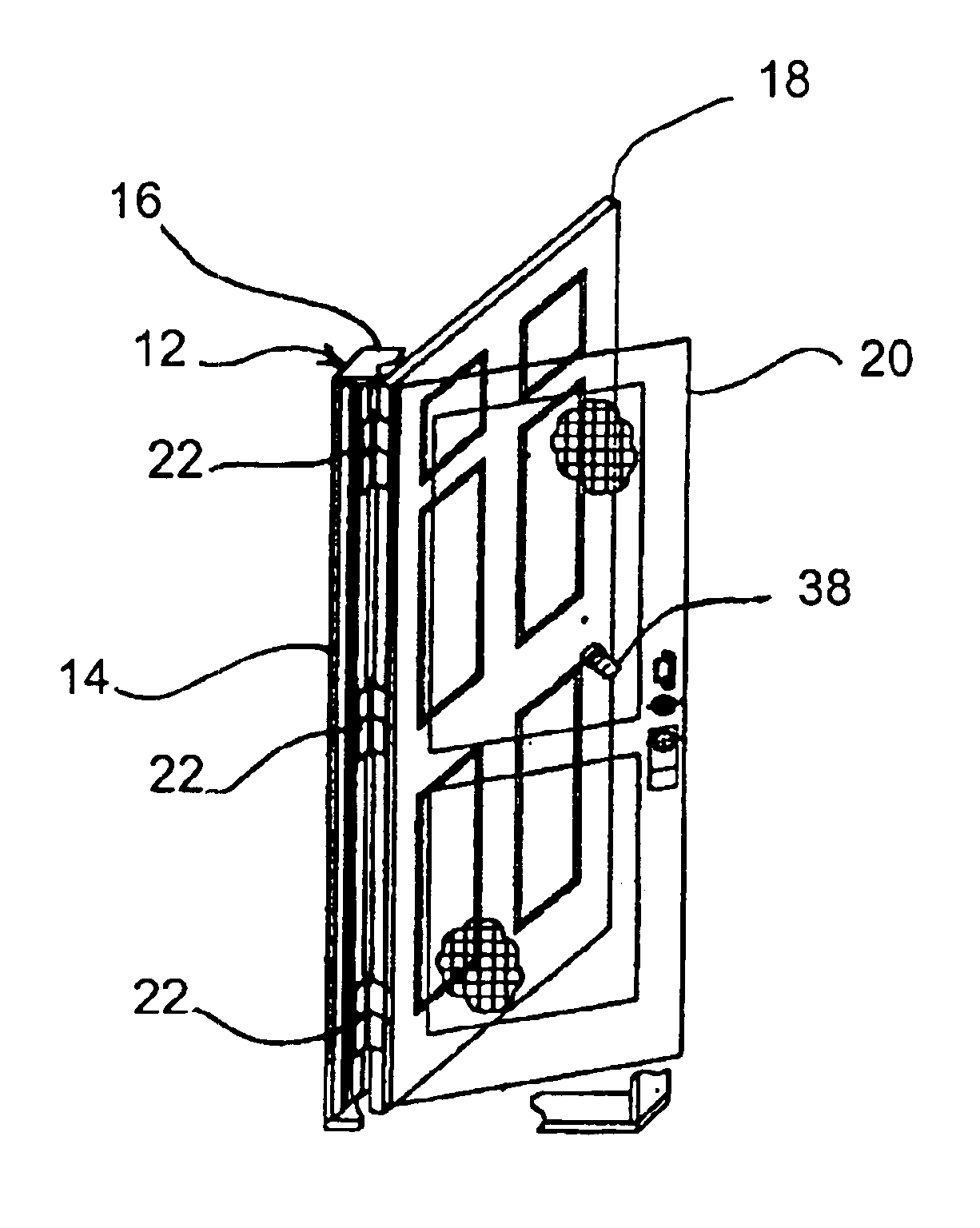
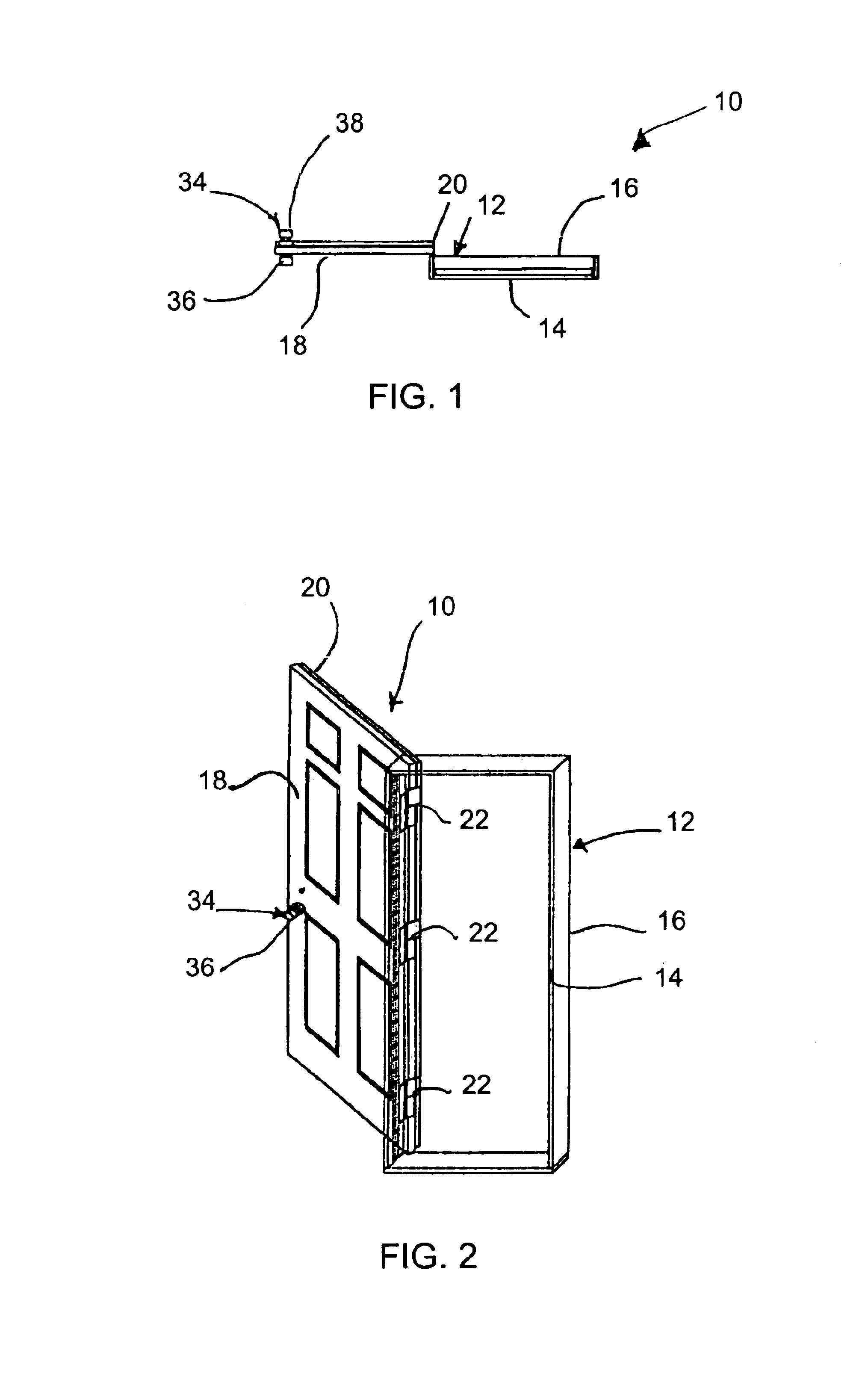
[0035]A door assembly in accordance with the subject invention is identified generally by the numeral 10 in FIGS. 1-8. The door assembly 10 is mounted to a door frame 12 that typically will be secured in an exterior wall of a building. The door frame 12 has an exterior side 14 and an interior side 16.

[0036]The door assembly 10 includes a barrier door 18 and a screen door 20. Although a screen door 20 is illustrated herein, it is understood that other environmental doors may be employed, such as a storm door or a combination storm and screen door.

[0037]The barrier door 18 and the screen door 20 are mounted to the door frame 12 by a plurality hinge assemblies 22 disposed for rotation about a common axis. As shown most clearly in FIGS. 9 and 10, each hinge assembly 22 includes first and second frame mounting plates 24 and 26, a barrier door mounting plate 28 and a screen door mounting plate 30. The first frame mounting plate 24 is opposed to the barrier door mounting plate 28, while th...


PUM


Abstract

A door assembly includes a barrier door that is hingedly rotatable about an axis of rotation. The door assembly further includes an environmental door that is hingedly rotatable about the axis of rotation. The barrier door and the environmental door can be rotated independently or in unison from opened positions to closed positions. The barrier door has a handle and the environmental door has a hole through which the handle can pass so that the barrier door handle can be accessed through the environmental door. The environmental door also has a cover for selectively closing the handle hole.

Description

[0001]This application claims the benefit of U.S. Provisional Application Ser. No. 60 / 441,918, filed on Jan. 22, 2003.BACKGROUND OF THE INVENTION[0002]1. Field of the Invention[0003]The invention relates to a door assembly with a barrier door and an environmental door that can be hingedly rotated relative to an opening either independently of one another or in unison.[0004]2. Description of the Related Art[0005]Exterior doorways to most residential buildings and some commercial buildings are provided with a pair of hinged doors. The first door is referred to herein as a barrier door and has sufficient structural integrity to control access to the building. Thus, the barrier door typically will have a lock that can be opened manually from the inside of the building, but requires a key for unlocking from the outside of the building. The barrier door typically opens inwardly to the building. The second door on the typical exterior doorway is referred to herein as an environmental door ...

Claims


Application Information

Patent Timeline
IPC IPC(8): E05D3/00E05D3/04E06B5/00E06B9/02E06B3/70E05C7/02
CPCE05C7/02E05D3/04E06B3/70E06B5/003E06B9/02E06B9/52E06B2009/005E05Y2900/132Y10S292/02
Inventor BUTLER, BRUCE
Owner BUTLER DOOR
Why Eureka
Try Eureka